Microwave heating apparatus and method

一种微波加热装置、微波加热的技术,应用在微波加热、电热装置、电加热燃料等方向,能够解决损伤触感、发黏等问题,达到阻止温度下降、阻止温度的下降的效果

Inactive Publication Date: 2004-11-10
PANASONIC CORP
View PDF1 Cites 1 Cited by
  • Summary
  • Abstract
  • Description
  • Claims
  • Application Information

AI Technical Summary

Problems solved by technology

For this reason, when thawing frozen bread, it prevents food from drying out, but the surface that should be dried becomes sticky, greatly impairing the texture

Method used


Image

  • Microwave heating apparatus and method
  • Microwave heating apparatus and method
  • Microwave heating apparatus and method

Examples


Embodiment 1

[0023] Next, a first embodiment of the present invention will be described with reference to the drawings.

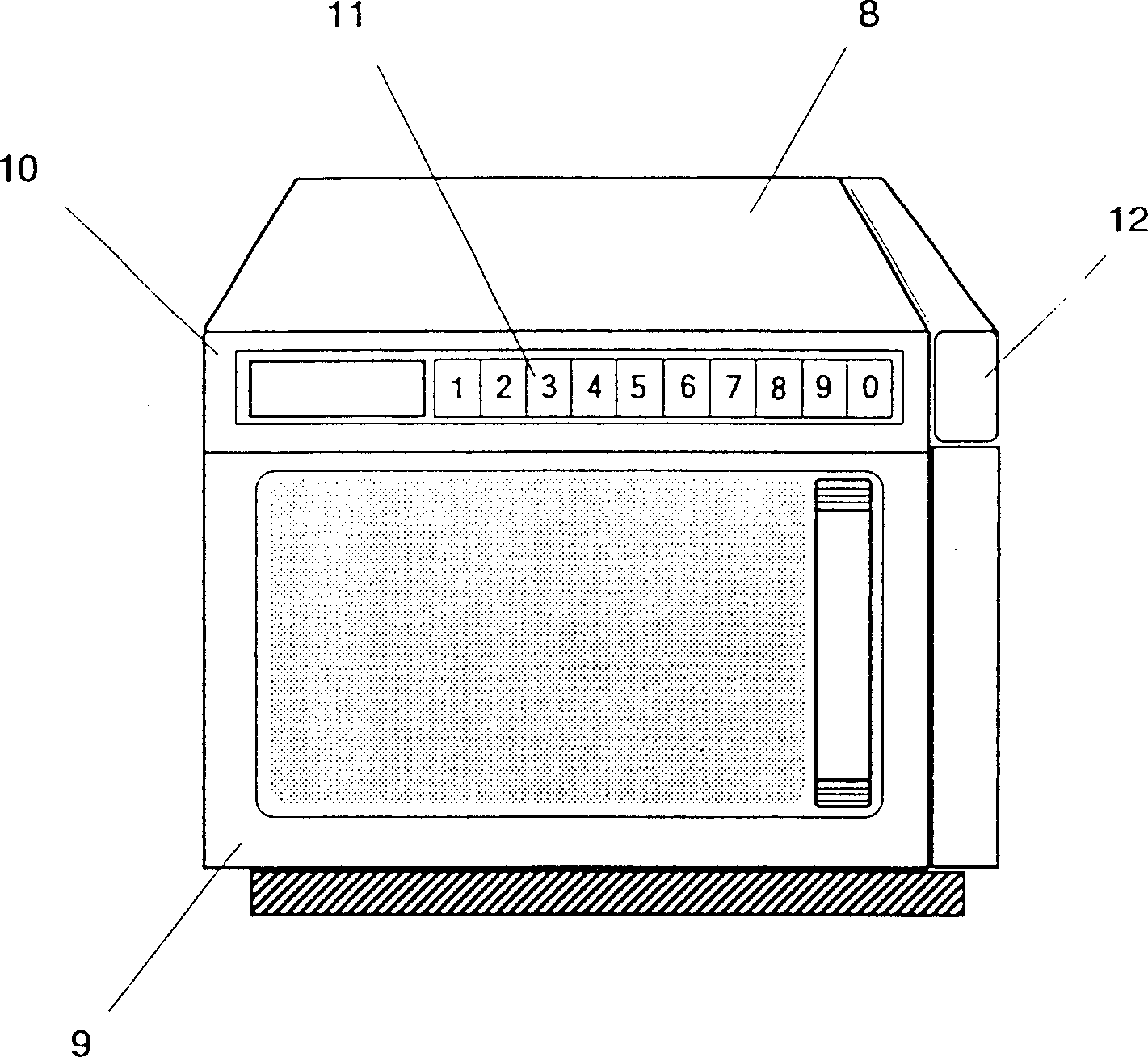
[0024] figure 2 It is the external view of the microwave heating device of the present invention. A door body 9 is pivotally supported in front of the main body 8 in a freely openable and closable manner, and is used to block the opening of the heating chamber for accommodating food. The heating instruction key 11 is arranged on the operation panel 10, so that the codes input by one digit or digits correspond to the types and quantities of food, storage temperature (freezing or quick freezing storage), heating temperature and other factors that affect the heating method. This is sent as a command to the control unit described later. A water supply tank 12 is detachably arranged on the right side of the main body.

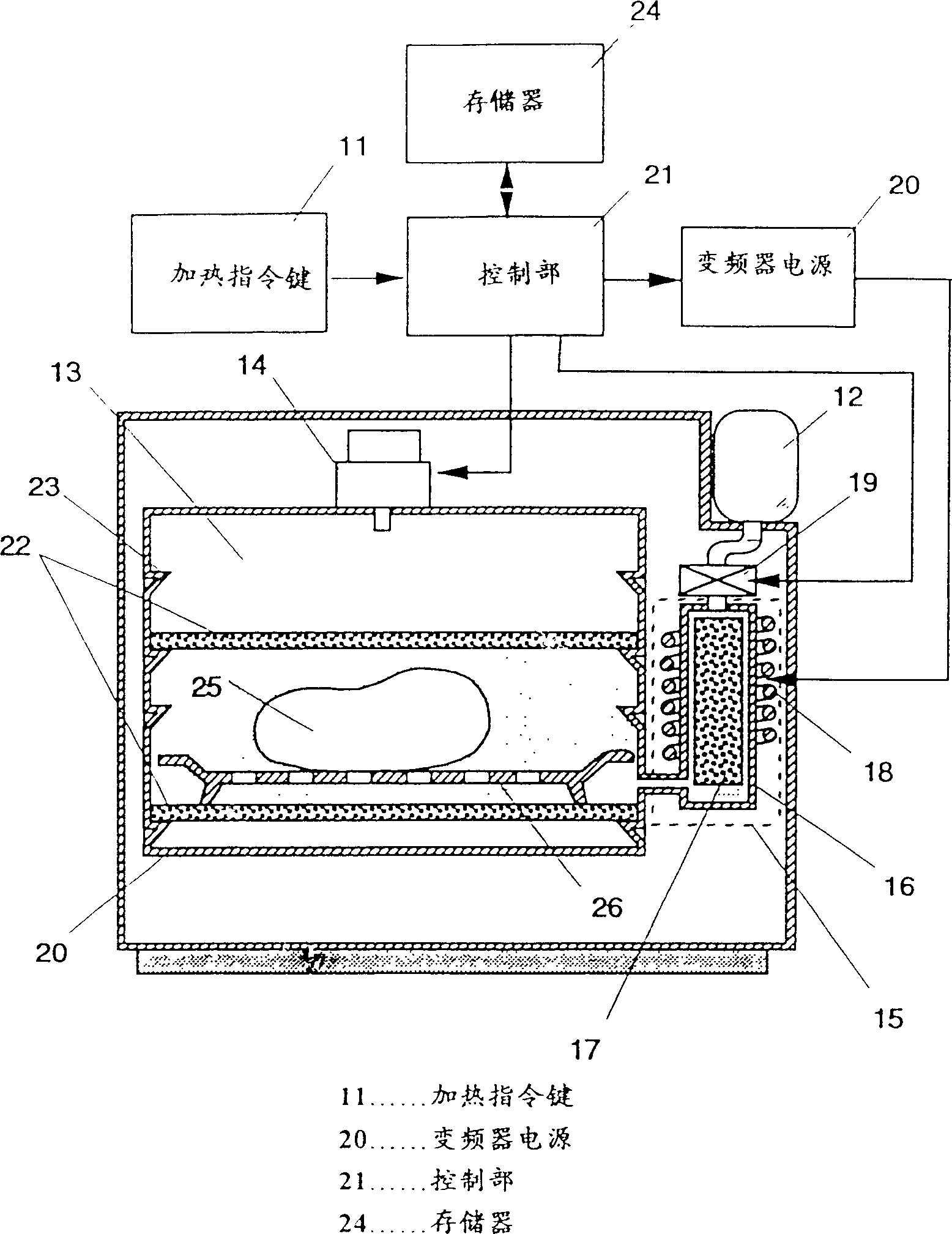
[0025] figure 1 In order to show the front sectional view of the heating chamber of the first embodiment of the present invention, a magnetron 14 as a ...

Embodiment 2

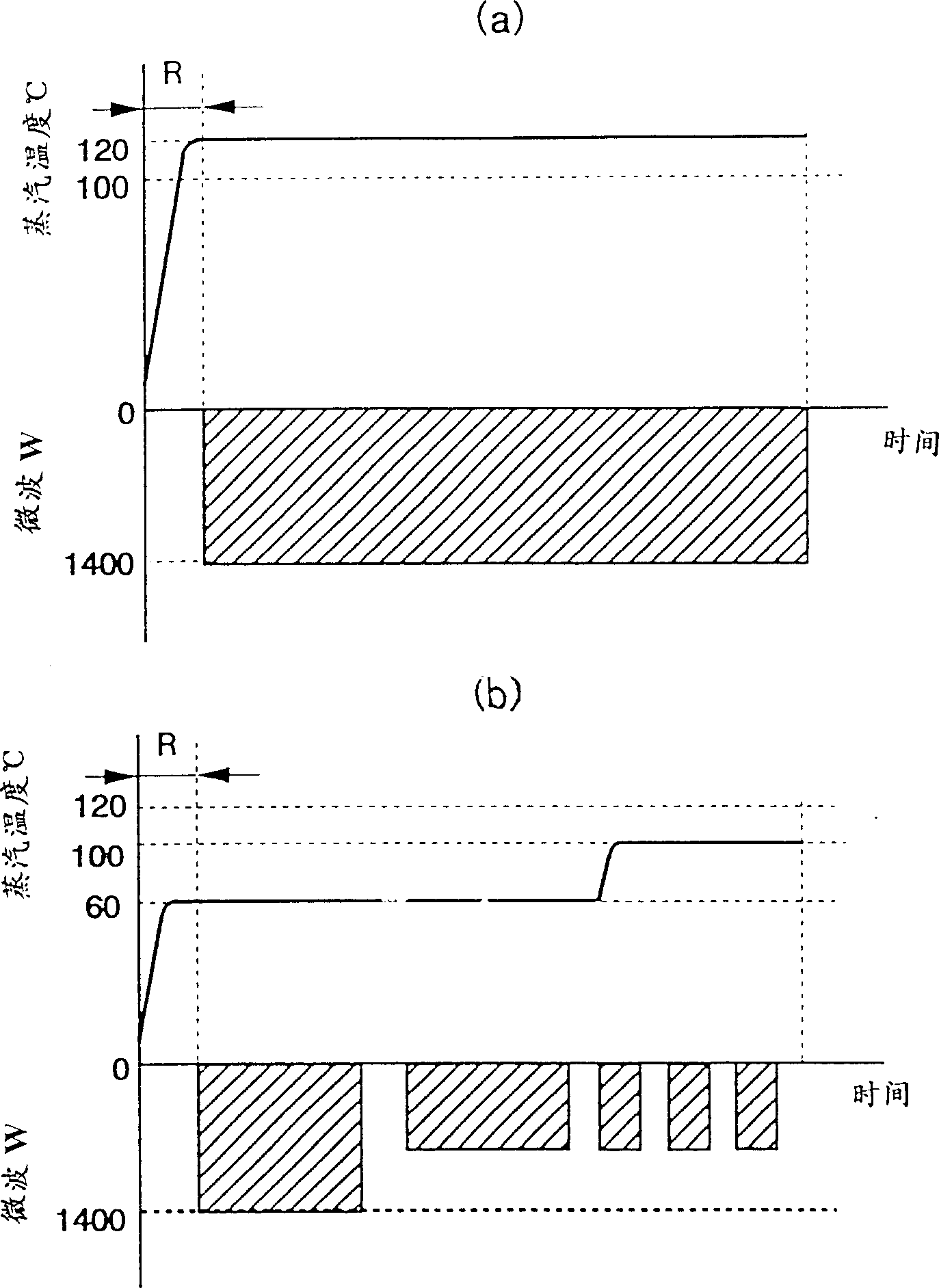
[0041] Figure (b) shows an example of changing the steam temperature in the heating chamber during the heating process. The first half is switched to a medium-humid state of about 60°C, and the second half is switched to superheated steam of 120°C. Microwaves also decrease sequentially. This comes into play in the heating of foods such as frozen bread and fried foods where it is desired to have a drier surface. That is, while preventing the drying of food with the unsaturated steam in the first half, the unevenness of microwave heating is slightly alleviated, and then the superheated steam in the second half keeps the surface dry.

[0042] The steam temperature in the first half is the best choice according to the food condition. In the experiment, the temperature of about 60°C shown in the figure was used for frozen bread, and the slightly higher temperature of about 80°C was used for fried food, and good results were obtained. In addition, in the reheating of steamed foods...

Embodiment 3

[0044] Figure 4 In order to show the front sectional view of the heating chamber in other embodiments, two magnetrons 14 are arranged on the top and bottom surfaces of the heating chamber in this embodiment. This up and down power supply is a practical technology commonly used in commercial microwave ovens, and it is possible to obtain a high output while maintaining a good electric field distribution. The object to be heated 25 is not placed on the carrier vessel, but placed directly on the temperature raising partition wall 22 on the bottom surface. Through-holes 27 are pierced through the heating partition wall on the bottom surface, and superheated steam is discharged from the steam generator 15 to the bottom surface of the heating chamber 13 .

[0045] In this configuration, the temperature raising partition wall 22 on the bottom surface absorbs microwaves to raise the temperature, and the heat is directly transferred to the object to be heated, so the heating efficienc...


PUM


Abstract

An object such as food is heated favorably by means of microwaves while enclosing the food with superheated steam. The apparatus comprises a heating chamber in which an object to be heated is put, steam generating means for supplying superheated steam to the heating chamber, superheated steam maintaining means provided in the heating chamber to prevent the temperature of the superheated steam in the heating chamber from lowering, and microwave generating means for irradiating the object with microwaves. The object placed in the heating chamber is heated in superheated steam with microwaves, so that the food is efficiently heated from inside and outside and the food is not wetted.

Description

technical field [0001] The present invention relates to a heating device which utilizes microwaves and can rapidly heat various food and other objects to be heated while maintaining good quality. Background technique [0002] As a conventional heating device of this type, there is, for example, a food thawing type cooking oven described in Japanese Patent Publication No. Sho 55-51541. Figure 5 The configuration is shown, in which a stirrer 3 is provided on the top surface 2 in a freely sealable furnace 1 , and a magnetron irradiation unit 4 is arranged near the stirrer 3 . There is a food rack 5 which can be freely attached and disassembled in the furnace 1, and a liquid container 6 for water, oil, etc. is arranged below it, and a heater 7 such as an electric heater is arranged below it. Combination of these magnetron irradiating parts 4 , liquid pan 6 and heater 7 can simultaneously utilize heating by magnetron irradiation from above and steam heating by boiling water from...

Claims


Application Information

Patent Timeline
Patent Type & Authority Patents(China)
IPC IPC(8): H05B11/00A23L3/365F24C7/02H05B6/80
CPCH05B6/6479F24C7/02
Inventor 植田茂树稻田育弘内山智美
Owner PANASONIC CORP
Why Eureka
Try Eureka