

Heald bar selecting mechanism of jacquard machine
A technology for selecting mechanism and jacquard machine, applied in the direction of jacquard machine, textile, textile and paper making, etc., can solve the problems of many components and complex structure, and achieve the effect of low manufacturing cost, simplified structure and low temperature rise
- Summary
- Abstract
- Description
- Claims
- Application Information
AI Technical Summary
Problems solved by technology
Method used
Image

Examples
no. 1 Embodiment
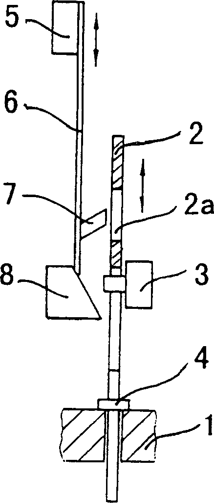
[0019] figure 1 It is a structural schematic diagram of the first embodiment of the present invention. The mechanism consists of a bracket 1, a reciprocating heald rod 2, an electromagnet 3, a stopper 4 fixed on the heald rod 2, a reciprocating lifting knife 5, and a sheet elastic body 6 fixed to the lifting knife 5 at one end. , is fixed on the support 1 and consists of a suction device 8; the heald rod 2 and the sheet elastic body 6 are respectively provided with engaging locking devices 2a and 7 that can make the heald rod 2 and the sheet elastic body 6 engage with each other; the support 1 and the sheet elastic body 6 The electromagnet 3 is fixed; the suction aid device 8 is a fixed protrusion, and the surface acting on the sheet elastic body 6 is a curved surface; the iron core of the electromagnet 3 acts on the suction aid device 8 and the sheet elastic body 6 surface.
[0020] This mechanism is under the engaged locking device 2a and 7 engagement state, and when lifti...
no. 2 Embodiment
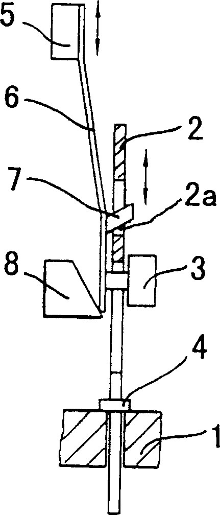
[0023] Figure 4 It is a structural schematic diagram of the second embodiment of the present invention. This mechanism is except suction device 8, and other structures are identical with the first embodiment; Suction device 8 is made up of slide block 8a, leaf spring 8b, moving block 8c; The other end is fixed on the bracket 1; the slider 8a has a chute, and the sheet elastic body 6 can reciprocate in the chute; the moving block 8c is a reciprocating moving block, and its moving direction is reciprocating with the lifting knife 5 The direction is vertical; the slider 8a and the sheet elastic body 6 are pushed close to the electromagnet 3 by the moving block 8c, and the slider 8a leaves the electromagnet 3 by the elastic restoring force of the sheet spring 8b.
[0024] This mechanism is under the engaged locking device 2a and 7 engagement state, and when lifting knife 5 moves toward suction aid 8 from the limit position farthest away from suction aid 8 (as Figure 5 State sh...
no. 3 Embodiment
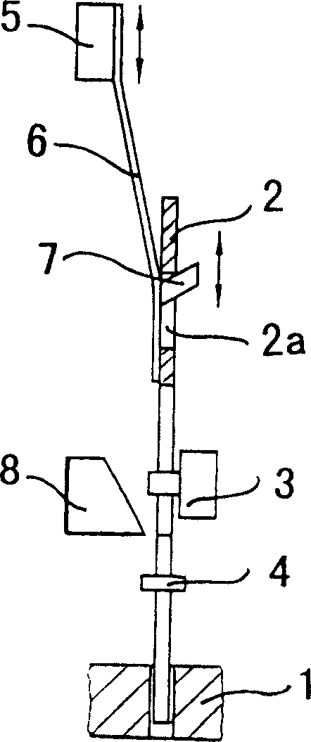
[0027] Figure 7 It is a structural schematic diagram of the third embodiment of the present invention. The mechanism is the same as the first embodiment except for the suction device 8; the suction device 8 is a reciprocating moving block whose direction of motion is perpendicular to the reciprocating direction of the lifting knife 5, and he can push the sheet elastic body 6 Attach the solenoid 3.
[0028] This mechanism is under the engaged locking device 2a and 7 engagement state, and when lifting knife 5 moves toward suction aid 8 from the limit position farthest away from suction aid 8 (as Figure 8 State shown), the heald rod 2 and the lifting knife 5 move together, before the lifting knife 5 reaches the limit position close to the suction device 8, first, the heald rod 2 rests on the support 1 through the stopper 4, and the heald rod 2 stops moving , the engagement locking devices 2a and 7 are disengaged from the engagement state, and the deformation of the sheet elas...
PUM
 Abstract
Description
Claims
Application Information