

Conical cycloid wheel planet transmission means
A technology of planetary transmission and conical pendulum, which is applied in the direction of gear transmission, transmission, belt/chain/gear, etc., can solve the problems of manufacturing difficulties, affecting transmission accuracy, low bearing capacity, etc., and achieve high processing accuracy and efficiency. The effect of high contact strength and improved load-carrying capacity
- Summary
- Abstract
- Description
- Claims
- Application Information
AI Technical Summary
Problems solved by technology
Method used
Image

Examples
Embodiment Construction
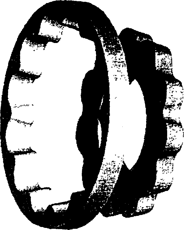
[0019] exist figure 1 Among them, the conical internal gear with the same cone angle and the conical cycloid planetary gear form a conical cycloid planetary meshing pair; the tooth profile curve of the conical internal gear includes the working arc segment and the transition curve of the dedendum, and the conical The working arc section of any radial section of the internal gear is a concentric arc; the tooth profile curve of the conical cycloid planetary gear is the equidistant line of the short cycloid, and the radial section of any radial section of the conical cycloid planetary The tooth profile curves are mutually equidistant lines.
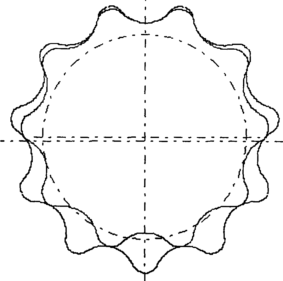
[0020] exist figure 2 Among them, the meshing transmission of any radial section of the conical cycloid planetary meshing pair is a precise meshing cycloid planetary transmission; the working arc radius of the conical internal gear changes continuously along the axial direction, while the conical cycloid The tooth profile curve of the pla...
PUM
 Abstract
Description
Claims
Application Information