
Etching method used in manufacturing fluid bearing

A fluid bearing and etching technology, applied to bearings, bearing components, shafts and bearings, etc., can solve the problems of non-wear resistance, insufficient rigidity and hardness of plastic bearings, and achieve the effects of easy integration, reduced production, and simplified manufacturing processes

Inactive Publication Date: 2005-02-23
IND TECH RES INST
View PDF2 Cites 0 Cited by
  • Summary
  • Abstract
  • Description
  • Claims
  • Application Information

AI Technical Summary

Problems solved by technology

However, the rigidity and hardness of the plastic bearing itself is insufficient, and it has the disadvantage of not being wear-resistant

Method used


Image

  • Etching method used in manufacturing fluid bearing
  • Etching method used in manufacturing fluid bearing
  • Etching method used in manufacturing fluid bearing

Examples


Embodiment Construction

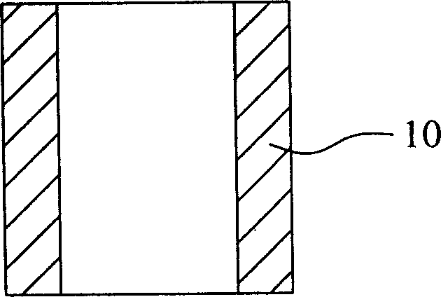
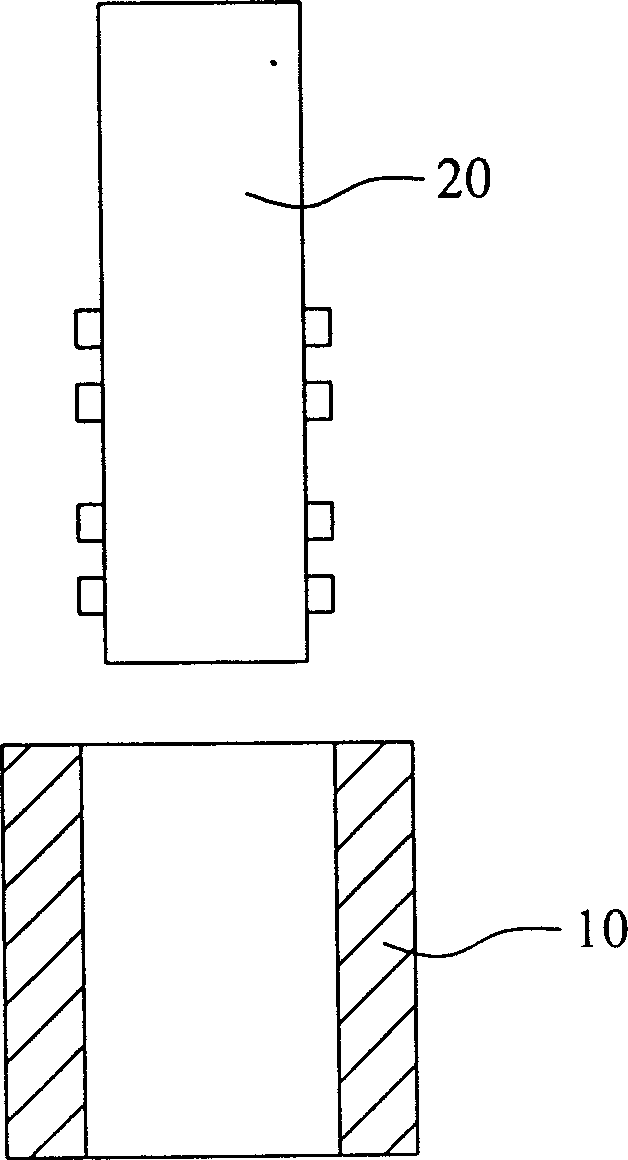
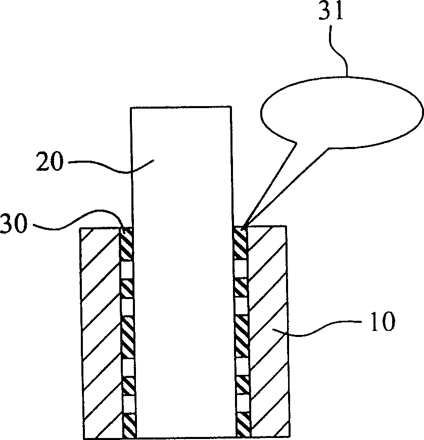
[0020] The technology disclosed in the present invention is an etching method applied to the manufacture of fluid bearings. The present invention uses a spraying mandrel as a mask of the bearing material, and then injects protective material to form a protective pattern on the inner diameter of the fluid bearing, which is like the photoresist pattern in photolithography. After pulling out the mandrel for spraying, etch the bearing material to form the required oil groove on the inner diameter. Finally, the etchant is cleaned and its protective pattern is removed.

[0021] In order to describe the present invention in more detail, the process steps of the embodiment of the present invention are described in detail below with reference to the accompanying drawings. Please refer to Figure 1 to Figure 8 , Figure 1 to Figure 8 It is a schematic diagram of the process steps of the embodiment of the etching method applied to the manufacture of the fluid bearing of the present inve...


PUM


Abstract

An etching technology for preparing fluid bearing includes using a mandrel for spraying as the mask of raw bearing material, filling the protecting material in the inner part of fluid bearing to generate the protecting pattern, pulling up said mandrel, etching to form the needed oil slot, and washing to remove the etching liquid and protecting pattern. Its advantages are high productivity and low cost.

Description

technical field [0001] The invention relates to an etching method applied to the manufacture of a fluid bearing, in particular to a method for manufacturing an oil groove in the inner diameter part of the fluid bearing. Background technique [0002] In terms of mechanical design, when making passive fluid bearings, it is necessary to design oil grooves on the inner diameter of the bearings, so that the bearings can generate oil film pressure and oil seal effects during operation. Generally, the internal oil groove of the bearing is manufactured by traditional cutting methods; but today's motors tend to be smaller and smaller, it is not easy to manufacture high-precision micro motors, and the depth, width and inner diameter of the oil groove of the micro motor The concentricity requirements are very strict. If it is produced by the traditional machining method of cutting, there will be problems such as burrs, poor concentricity of the oil groove, wear of the tool, and diffic...

Claims


Application Information

Patent Timeline
Patent Type & Authority Patents(China)
IPC IPC(8): F16C17/02F16C33/14
Inventor 章广贤徐弘光
Owner IND TECH RES INST
Learn More