Abrading head for chemical mechanical abrading

A technology of chemical machinery and grinding head, which is applied in the direction of machine tools, grinding machines, grinding/polishing equipment, etc. suitable for grinding workpiece planes, and can solve the problem of reducing the process yield, uneven grinding effect, and increasing the difficulty of integrated circuit manufacturing, etc. question

Inactive Publication Date: 2005-05-04
UNITED MICROELECTRONICS CORP
View PDF0 Cites 2 Cited by
  • Summary
  • Abstract
  • Description
  • Claims
  • Application Information

AI Technical Summary

Problems solved by technology

However, the rigidity of the knife edge 110 and the bending of the elastic film 112 during grinding will cause uneven grinding effects such as the fast belt effect, which will increase the difficulty of the integrated circuit process and reduce the yield of the process.

Method used


Image

  • Abrading head for chemical mechanical abrading
  • Abrading head for chemical mechanical abrading
  • Abrading head for chemical mechanical abrading

Examples


Embodiment Construction

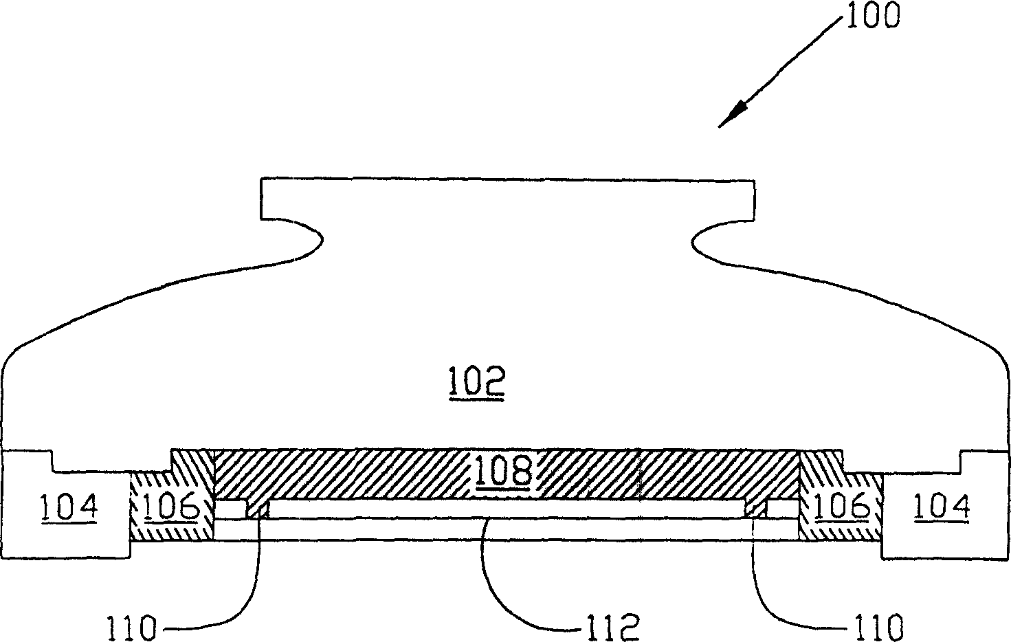
[0016] It must be noted here that the structure described below does not include a complete process. The present invention can be implemented by means of various process technologies, and only the processes and structures required for an understanding of the present invention are mentioned here. Hereinafter, the present invention will be described in detail according to the accompanying drawings. Please note that the drawings are in simple form and not drawn to scale, and the dimensions are exaggerated to facilitate understanding of the present invention.

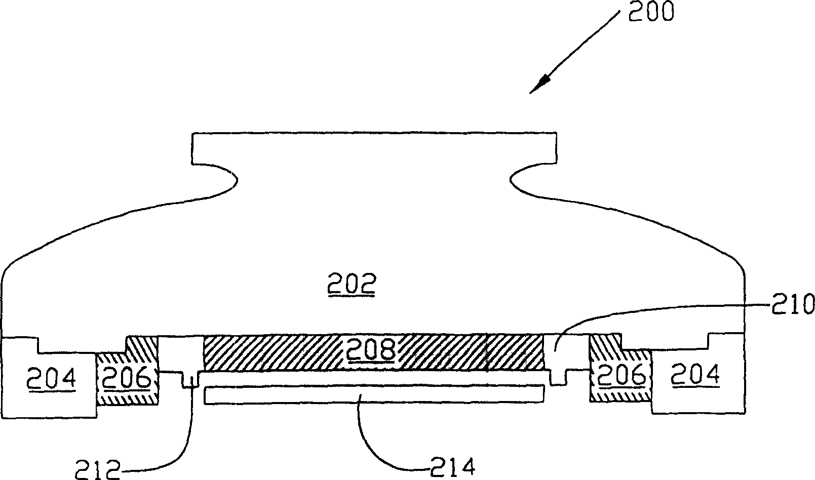
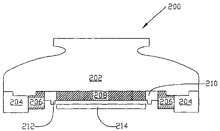
[0017] refer to figure 2 As shown, a polishing head 200 for chemical mechanical polishing of the present invention is shown. The grinding head 200 includes a main body 202, a retaining ring (Retaining Ring) 204, an edge pressure ring (Edge Load Ring) 206, a support plate 208, a knife edge ring (Incision Ring) 210 including a knife edge (Incision) 212 and an elastic Flexible Membrane 214 . During actual grinding, the pol...


PUM


Abstract

The invention discloses a grinding head for chemical mechanical grinding. The grinding head has a non-rigid knife-edge ring with non-rigid knife-edges protruding downward. The non-rigid knife-edge ring surrounds a support plate of the grinding head to replace the knife-edges on the traditional support plate. The grinding head also has an elastic film extending to the outer edge of the support plate, and the outer edge of the elastic film is a predetermined distance away from the knife edge.

Description

(1) Technical field [0001] The invention relates to a grinding head for chemical mechanical grinding, in particular to a grinding head for chemical mechanical grinding which can effectively increase the uniformity of grinding. (2) Background technology [0002] Integrated circuits are usually formed on a substrate, especially a silicon wafer, by sequentially depositing conductive layers, semiconductor layers, and dielectric layers. After the films are deposited, the films are then etched to form the circuits. After a series of deposition and etching processes of conductor layer, semiconductor layer and dielectric layer, the edge of the substrate, the exposed part of the substrate or the surface of the uppermost film becomes very uneven. Uneven film surfaces can cause problems in integrated circuit fabrication. It is therefore necessary to planarize the film surface after each film deposition. [0003] Chemical mechanical polishing is the most commonly used planarization p...

Claims


Application Information

Patent Timeline
Patent Type & Authority Patents(China)
IPC IPC(8): B24B37/30H01L21/306
CPCB24B37/30H01L21/30625
Inventor 林进坤陈慈信赖建兴魏詠宗
Owner UNITED MICROELECTRONICS CORP
Why Eureka
Try Eureka