Optical switch

An optical switch and armature technology, applied in the field of optical switches, can solve problems such as increasing the total size, and achieve the effects of reducing the total size, reducing the number of parts, and high accuracy

Inactive Publication Date: 2005-06-01
MATSUSHITA ELECTRIC WORKS LTD
View PDF2 Cites 0 Cited by
  • Summary
  • Abstract
  • Description
  • Claims
  • Application Information

AI Technical Summary

Problems solved by technology

Thus, more space is required to clear the movement of the prism 31, thus increasing the overall size of the body 1

Method used


Image

  • Optical switch
  • Optical switch
  • Optical switch

Examples


no. 1 example

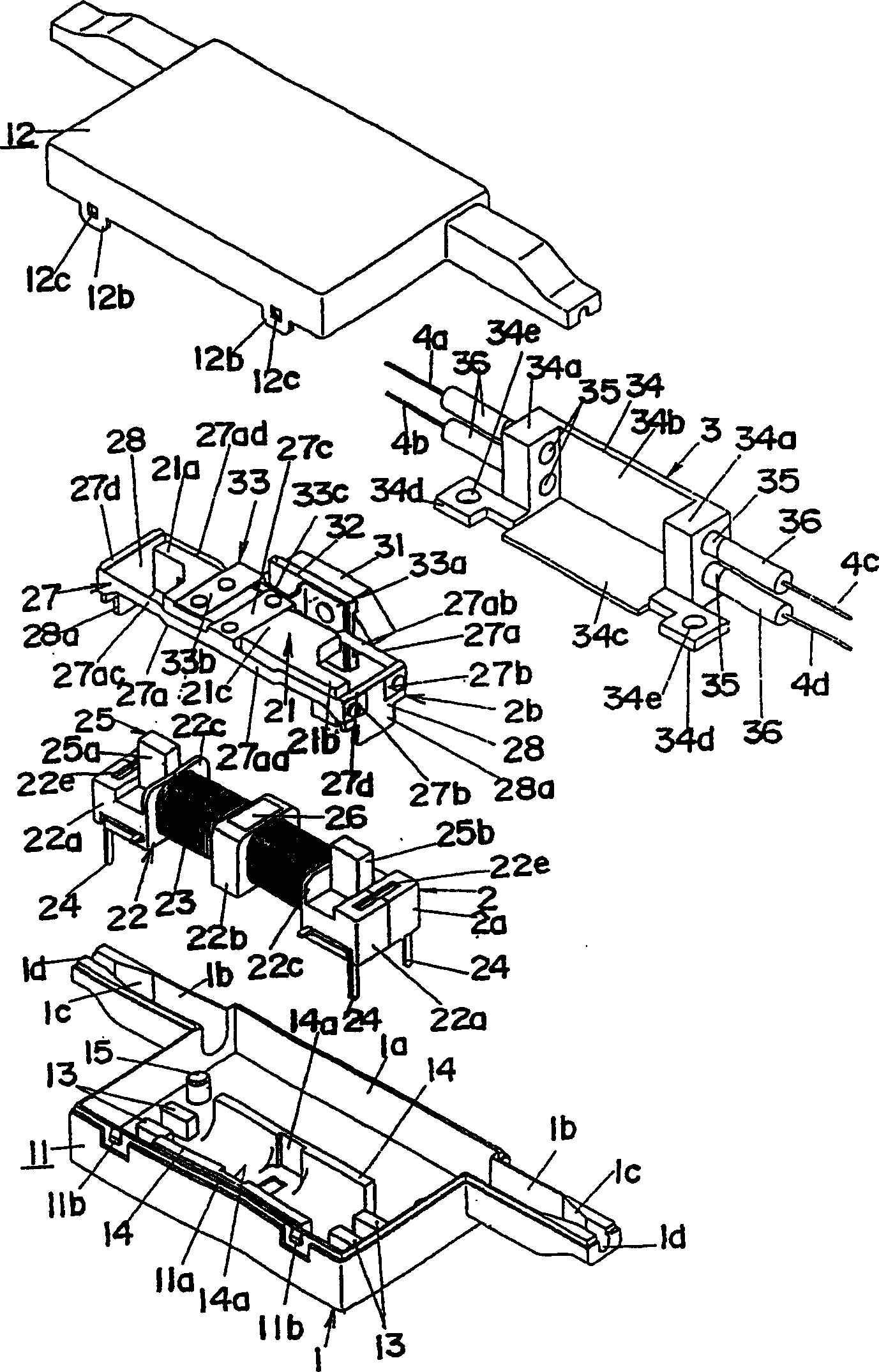
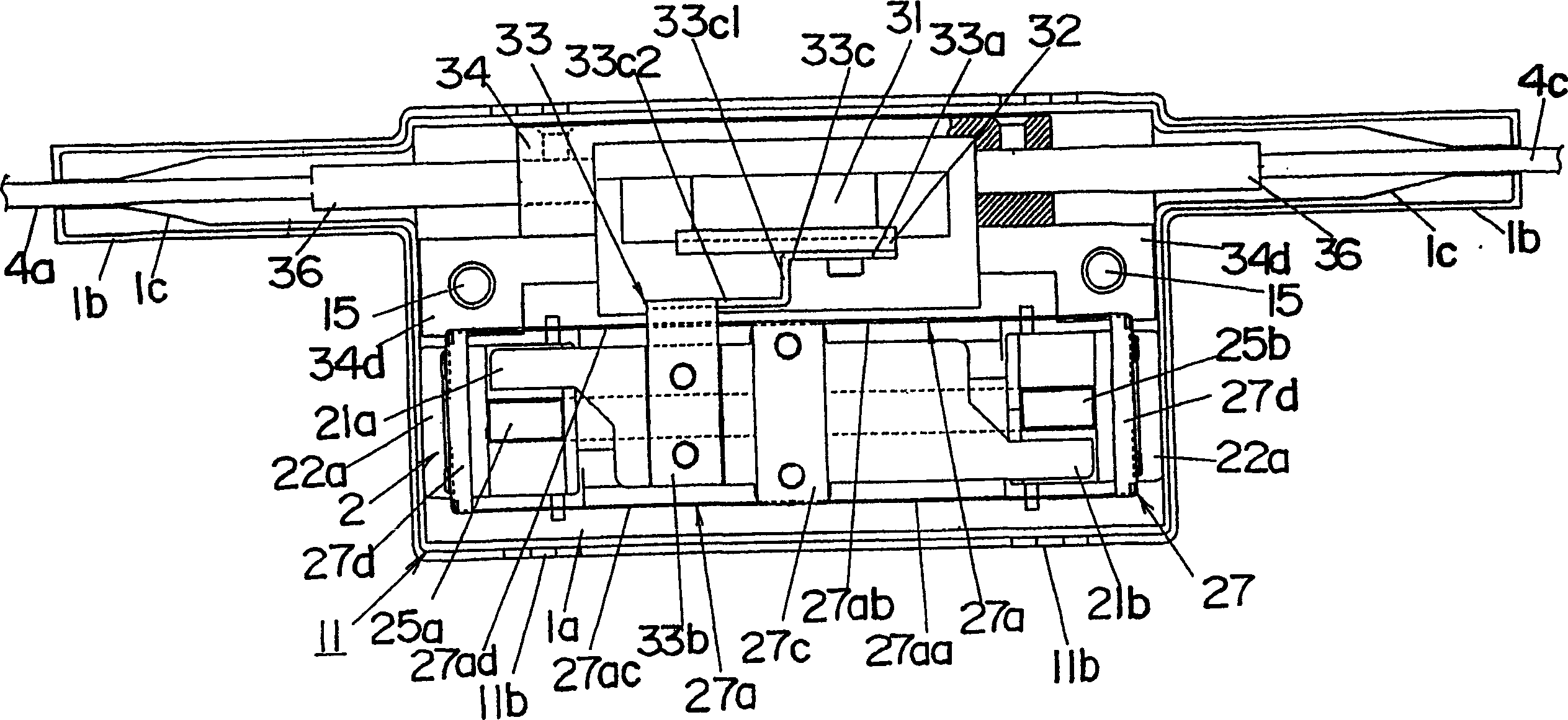
[0082] Refer below Picture 1-1 5 illustrates an optical switch of an embodiment of the present invention. The optical switch is of the 2×2 type for switching between two modes of an optical connection with four optical fibers 4a-4d; the connection between optical fiber 4a and optical fiber 4d and between optical fibers 4b and 4c, as shown in Fig. 15(a); the connections between the optical fiber 4a and the optical fiber 4c and between the optical fiber 4b and the optical fiber 4d are shown in FIG. 15(b). These two modes can be selected by actuating and inactivating a prism 31 arranged between one set of fibers 4a and 4b and the other set of fibers 4c and 4d. The prism 31 is movable along a direction perpendicular to the paper plane shown in FIG. 15 .

[0083] see Figure 1-3 , the optical switch of this embodiment includes an electromagnetic driver 2 with an armature 21 and an optical path selector 3 actuated by the action of the armature 21, used for switching and connecti...

no. 2 example

[0102] In the first embodiment, the permanent magnet 26 is mounted on the bobbin 22, in the second embodiment, as Figure 20 and21 As shown, a permanent magnet 26 is mounted to the longitudinal center of the armature 21 so as to face the electromagnet 2a. One pole of the permanent magnet 26 is magnetically coupled to the armature 21 for magnetization. Other components are the same as those of the first embodiment. The action of the electromagnetic drive 2 thus remains the same as in the first embodiment. Since the bobbin 22 of this embodiment does not need to include the magnet holder 22b, more space can be made for the coil 23 in its given size, unlike the first embodiment, thereby reducing power consumption. If the space for the coil 23 remains the same as that of the first embodiment, the size of the bobbin 22 can be reduced, whereby the overall size of the body 1 can be minimized.

no. 3 example

[0104] In the foregoing embodiments, when the prism 31 is mounted on the armature 21 by means of the prism mounting assembly (fixing plate 32 and adjusting plate 33), it is mounted to the prism mounting seat 29 provided integrally with one side of the armature 21, as Figure 22-24 shown. More specifically, prism 31 is glued to prism mount 29 . The prism mount 29 is located at the longitudinal center of the armature 21 so as to extend through the spring piece 27a. The prism mount 29 has a fitting groove 29a provided at its end for receiving the middle portion of the spring piece 27a (one end of the connection piece 27c). This allows the prism mount 29 to be integrally formed with the armature 21 while simplifying the shape of the balance spring 27 . Other components and actions are the same as those of the first embodiment.


PUM


Abstract

Provide an optical switch for switching the optical path between the collimating lens (35) optically coupled to the end of the corresponding optical fiber (4a-4d) by the advancing and retracting movement of the prism (31), including an armature (21) arranged to fix the prism (31) ) and the electromagnetic driver (2) and the leaf spring (27) of the coil body (2a) driven by the magnetic action to drive the armature (21) to move, the leaf spring mainly includes four spring pieces (27aa-27ad) extending in parallel and one end is connected to the body (1) and the other end are connected with the armature (21), and the armature (21) and the prism (31) are fixed in space for linear movement. The electromagnetic driver (2) and the prism (31) are arranged adjacent to each other along the moving direction of the armature (2). When the optical switch operates, the armature (21) and the prism (31) can linearly move along the optical line between the vertical lenses (35). This allows the prism to move linearly, unlike any conventional arrangement in which the moving part of the fixed prism moves around a pivot. The overall size of the body can be reduced by eliminating the need for dead space to limit the pivotal movement of the prism.

Description

technical field [0001] The present invention relates to an optical switch for switching combinations of optical paths between a plurality of optical fibers. Background technique [0002] Typically, an optical switch is provided for switching the optical path between a plurality of collimating lenses optically coupled to corresponding optical fibers through prisms advancing and retracting between the two sets of lenses. Some conventional optical switches have been disclosed having an electromagnetic driver provided with an armature mechanically connected to a prism (US Patent US 5999669 and Japanese Patent Laid-Open Publication 4-145409). [0003] The optical switch disclosed in US Pat. No. 5,999,669 has a prism 31 arranged to move back and forth between collimating lenses 35 optically coupled to corresponding optical fibers 4a-4c and located in the body 1 for switching optical paths , as shown in Figure 57. The prism 31 is mounted on one end of the arm 37, and the other en...

Claims


Application Information

Patent Timeline
Patent Type & Authority Patents(China)
IPC IPC(8): G02B26/08G02B6/35
CPCG02B6/3528G02B6/3546G02B6/3572G02B6/358G02B6/3582G02B26/08
Inventor 杉山贵则三原义博信时和弘
Owner MATSUSHITA ELECTRIC WORKS LTD
Why Eureka
Try Eureka