Method for distributing set information for connecting with external network
一种设定信息、外部网络的技术,应用在网络互连、特殊数据处理应用、通过路径配置进行数据交换等方向,能够解决IP地址变更、故障解决对策和网络负荷的调整困难、通信障碍等问题
- Summary
- Abstract
- Description
- Claims
- Application Information
AI Technical Summary
Problems solved by technology
Method used
Image
Examples
Embodiment 1
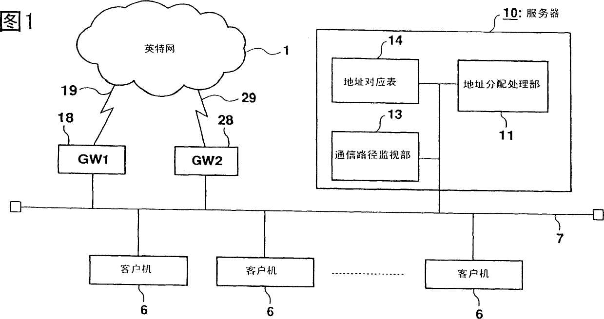
[0038] FIG. 1 is a block configuration diagram showing a client server system implementing a setting information distribution method for external network connection according to the present invention. The client-server system in this embodiment has a configuration in which one server 10 , two gateways 18 and 28 , and a plurality of clients 6 are connected to the LAN 7 . Except for the server 10, it is the same as the conventional example. Each client 6 can access the Internet 1 via any one of the gateways 18 , 28 . It is only necessary for the client 6 to have a function as a general-purpose DHCP client, and the unique functions of this embodiment are not necessary.
[0039] The server 10 is a server having the same function as a conventional DHCP server, and has a processing function of dynamically assigning an IP address corresponding to DHCP. Although it can be known by the processing described later, the content of the IP address assignment processing is different. The ...
Embodiment 2
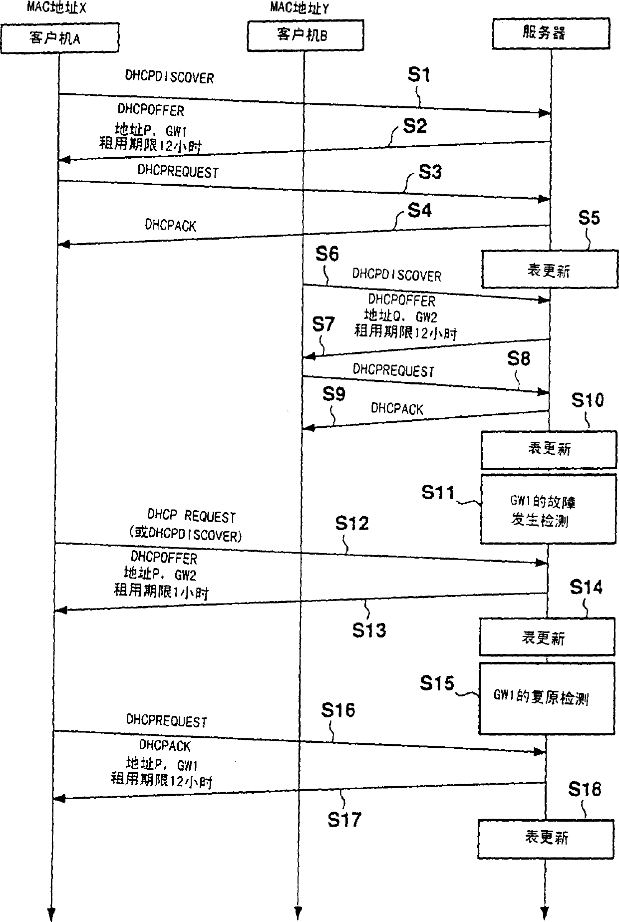
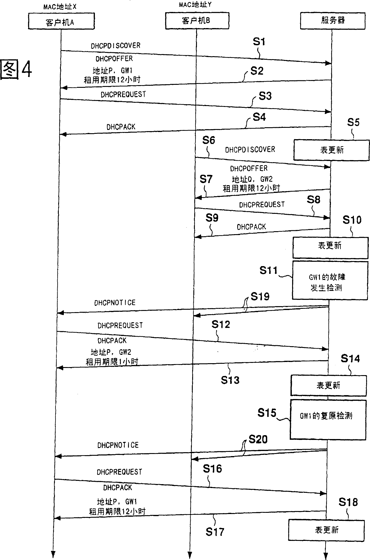
[0053] FIG. 4 is a diagram showing the communication procedure between the server and two clients in this embodiment. The same reference numerals are used for the same processing as in FIG. 3 , and descriptions thereof are appropriately omitted. In Embodiment 1 above, when GW1 is unavailable due to a failure or the like, client A sends a DHCPREQUEST message (assignment request) close to the lease term (exactly when 50% of the lease term has elapsed) (S12). Prior to this, when accessing the Internet 1, an error occurred, and a solution was requested. Therefore, this embodiment is characterized in that when the communication path monitoring unit 13 detects that a failure has occurred in the gateway 18 ( S11 ), it notifies the client 6 of the information at that time.
[0054] That is, when a failure of the gateway 18 is detected, the address assignment processing unit 11 broadcasts the information to the client 6 (S19). Since there is no information prepared for this broadcast...
Embodiment 3
[0060] FIG. 5 is a block diagram showing another customer service system implementing the setting information distribution method for external network connection according to the present invention. The customer service system in this embodiment is different from the above-mentioned embodiments in that it has multiple servers 10 , 20 , 30 . Each server 10, 20, 30 has the same function. In this embodiment, as shown in FIG. 5 , a case where a server system is constituted by three servers 10 , 20 , and 30 will be described as an example. Certainly, also can be two, also can be more than four. The number of gateways 18, 28, and 38 is three for convenience of description, but it is not necessary to match the number of servers. The gateways 18, 28, 38 themselves may be existing products the same as those in Embodiments 1 and 2.
[0061] One or more client computers 6 connected to the LAN 7 like this server system access the Internet 1 through any one of the gateways 18 , 28 , 38 a...
PUM
 Abstract
Description
Claims
Application Information
 - R&D
- Intellectual Property
- Life Sciences
- Materials
- Tech Scout
- Unparalleled Data Quality
- Higher Quality Content
- 60% Fewer Hallucinations
Browse by: Latest US Patents, China's latest patents, Technical Efficacy Thesaurus, Application Domain, Technology Topic, Popular Technical Reports.
© 2025 PatSnap. All rights reserved.Legal|Privacy policy|Modern Slavery Act Transparency Statement|Sitemap|About US| Contact US: help@patsnap.com


