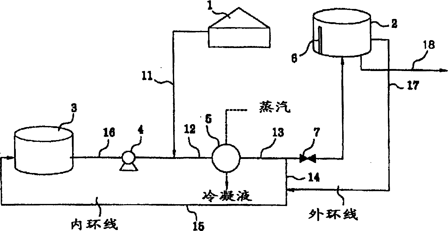
Method for removing deposited slag from crude oil trough and recovering oil from it
A technology for recovering oil and sludge, which is applied in the field of removing sludge in crude oil tanks and recovering oil from it, and can solve the problems of removal efficiency, cleaning time and economic benefits.
- Summary
- Abstract
- Description
- Claims
- Application Information
AI Technical Summary
Problems solved by technology
Method used
Image
Examples
Embodiment 1
[0087] Laboratory tests were performed to understand the mechanism of sludge melting in tanks. In a 3-liter beaker, the sludge was introduced until it reached a height of 10 cm, and heavy oil at atmospheric pressure equal to the volume of the sludge was placed on top of it. This way, the sludge will float to the surface, so a heavy tube was placed in the beaker to hold the sludge in place.
[0088] Atmospheric heavy oil is heated using a heat exchanger made of copper tubes, and water is circulated externally using a constant temperature bath as a heat source. The stirrer is centrally located and operates at a low speed of 20 rpm. Thus, the operating temperature is 65-80°C. A thermocouple with multiple tips was installed in the beaker to observe the change in the height of the sludge.
[0089] As a result of said test, it was determined that it takes about 4 hours to melt a sludge with a thickness of 10 cm, so this laboratory test can be scaled up to an actual refinery.
Embodiment 2
[0091] A test to detect the separation of inorganic substances in a separation tank.
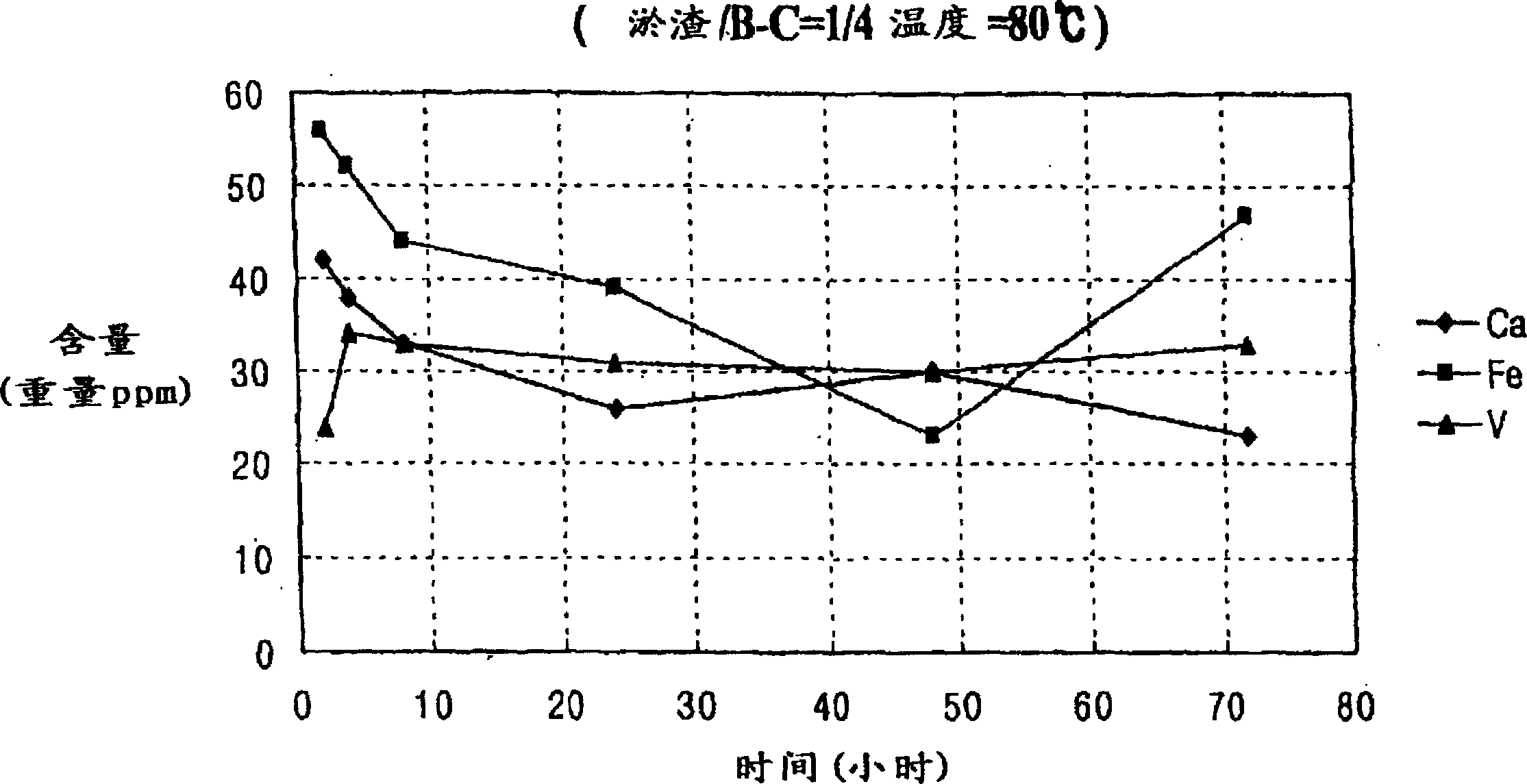
[0092] Sludge and atmospheric heavy oil (B-C, referring to atmospheric heavy oil in high-sulfur crude oil storage tank) were mixed in a 1:4 volume ratio in a 3-liter glass decanter, melted and stirred at 80°C. The sample kept at 80°C in the oven was extracted over time, and the content of inorganic substances and combustion loss were measured by ICP (Inductively Coupled Plasma).
[0093] The vanadium contained in the sludge does not affect the separation by precipitation because it exists in a mixed state with hydrocarbons. Inorganic substances that can be separated by precipitation are rust components produced by tank corrosion and components contained in brine. The sludge contains thousands to tens of thousands of ppm iron.
[0094] Separation over time within the upper and middle layers as image 3 and Figure 4 shown. In the case of samples in the upper and middle layers, the iron c...
Embodiment 3
[0097] In order to prove the effect of the present invention, the present invention is applied to the actual process. A One-Through test was performed using only 80° C. atmospheric heavy oil as a heat source without heat exchangers and pumps, thereby preferably determining required investment and technical efficiency. The crude oil storage tank used is a 750,000bbl tank for storage of crude oil with high sulfur content. Before the test, the accumulated amount of sludge in the tank was about 2,450 tons (about 16,000 bbl, assuming a specific gravity of 1).
[0098] The main purpose of the test was to demonstrate the efficiency of the sludge removal process, not using recovered oil, so 84,000bbl of 80°C atmospheric heavy oil was used as a heat source to observe the sludge height. In this way, the volume ratio of atmospheric heavy oil to sludge is 5.3:1. The normal-pressure heavy oil is passed into the crude oil storage tank through conventional pipelines.
[0099] Drain the cr...
PUM
| Property | Measurement | Unit |
|---|---|---|
| boiling point | aaaaa | aaaaa |
Abstract
Description
Claims
Application Information
 - R&D
- Intellectual Property
- Life Sciences
- Materials
- Tech Scout
- Unparalleled Data Quality
- Higher Quality Content
- 60% Fewer Hallucinations
Browse by: Latest US Patents, China's latest patents, Technical Efficacy Thesaurus, Application Domain, Technology Topic, Popular Technical Reports.
© 2025 PatSnap. All rights reserved.Legal|Privacy policy|Modern Slavery Act Transparency Statement|Sitemap|About US| Contact US: help@patsnap.com


