
Reference voltage generating circuit and generating method, display drive circuit and display

A reference voltage and generating circuit technology, applied in the direction of adjusting electric variables, static indicators, cathode ray tube indicators, etc., can solve the problem that the charge and discharge time cannot be fully guaranteed, the current of the ladder resistance increases, and the resistance ratio of the ladder resistance Small problems, to achieve the effect of shortening charging time, reducing current consumption, and reducing charge and discharge

Inactive Publication Date: 2005-12-21
SEIKO EPSON CORP
View PDF0 Cites 1 Cited by
  • Summary
  • Abstract
  • Description
  • Claims
  • Application Information

AI Technical Summary

Problems solved by technology

Therefore, the power supply voltage into which the ladder-shaped resistors are inserted is alternately applied according to the polarity inversion cycle, and thus the required charge and discharge time cannot be fully guaranteed, and the resistance ratio of the ladder-shaped resistors must be small
In this way, the current flowing through the ladder resistor will increase, resulting in an increase in power consumption

Method used


Image

  • Reference voltage generating circuit and generating method, display drive circuit and display
  • Reference voltage generating circuit and generating method, display drive circuit and display
  • Reference voltage generating circuit and generating method, display drive circuit and display

Examples


Embodiment Construction

[0062] The best mode of the present invention will be described in detail below using the drawings. In addition, the embodiments described below do not unduly limit the content of the present invention described in the claims. In addition, not all the configurations described below are essential configuration requirements of the present invention.

[0063] The reference voltage generation circuit in this embodiment can be used as a gamma correction circuit. This gamma correction circuit is included in a display drive circuit. The display driving circuit can be used for driving an electro-optical device whose optical properties are changed by an applied voltage, such as a liquid crystal device.

[0064] Although a case where the reference voltage generating circuit of this embodiment is used in a liquid crystal device will be described below, it is not limited thereto and can be applied to other display devices.

[0065] 1. Display device

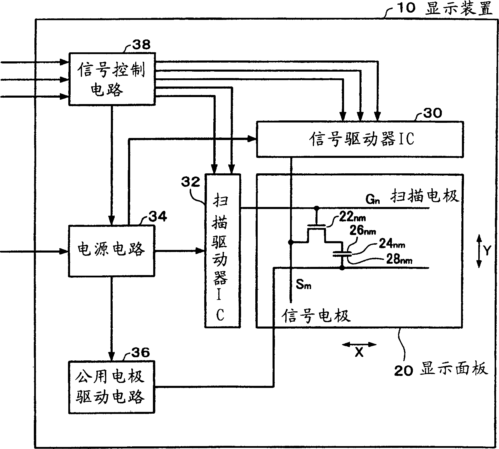
[0066] figure 1 An outline of th...


PUM


Abstract

A reference voltage generation circuit for driving a liquid crystal display comprises a positive polarity ladder resistor circuit including a first ladder resistor circuit (212) between first and second power source lines supplied with first and second power source voltages (VDD, VSS), respectively, and a negative polarity ladder resistor circuit including a second ladder resistor circuit (222) between the first and second power source lines. First to i-th reference voltage output switching circuits (VSW1-VSWi) are respectively inserted between first to i-th division nodes (ND 1 -ND i ) of the first ladder resistor circuit (212), where i is an integer larger than or equal to 2, and first to i-th reference voltage output nodes (VND 1 -VND i ). (i + 1)th to 2i-th reference voltage output switching circuits (VSW(i+1)-VSW2i) are respectively inserted between (i + 1)th to 2i-th division nodes (ND i+1 -ND 2i ) of the second ladder resistor circuit and the first to i-th reference voltage output nodes. When polarity inversion of a voltage outputted by a polarity inversion drive system at a given polarity inversion period is repeated, the first to i-th reference voltage output switching circuits are switched on during a positive polarity driving period and switched off during a negative polarity driving period; and the (i + 1)th to 2i-th reference voltage output switching circuits are switched off during the positive polarity driving period and switched on during the negative polarity driving period.

Description

technical field [0001] The invention relates to a reference voltage generating circuit, a display driving circuit, a display device and a reference voltage generating method. technical background [0002] Display devices typified by electro-optical devices such as liquid crystal devices are required to be smaller in size and higher in precision. Most of these liquid crystal devices achieve low power consumption and are mounted on portable electronic devices. For example, when mounted as a display unit of a mobile phone, image display with rich hues by multi-coloring is required. [0003] In general, a video signal used for image display is gamma-corrected according to display characteristics of a display device. This gamma correction is implemented by a gamma correction circuit (a reference voltage generation circuit in a broad sense). Taking a liquid crystal device as an example, a gamma correction circuit generates a voltage corresponding to the transmittance of a pixel...

Claims


Application Information

Patent Timeline
Patent Type & Authority Patents(China)
IPC IPC(8): G02F1/133G05F1/10G09G3/20G09G3/32G09G3/36G09G5/06
CPCG09G3/2011G09G3/32G09G3/3233G09G3/325G09G3/3614G09G3/3685G09G3/3688G09G3/3696G09G5/06G09G2300/0842G09G2300/0861G09G2310/0248G09G2310/0251G09G2310/027G09G2310/04G09G2320/0276G09G3/36
Inventor 森田晶
Owner SEIKO EPSON CORP
Learn More