Communication system and communication method

A technology of a communication system and a communication method, which is applied in the field of transmission power control, can solve the problems of insufficient traffic control, unevenness, and interference traffic distribution of multiple cells, and achieve the goal of eliminating uneven traffic distribution and reducing interference Effect

Inactive Publication Date: 2006-01-18
MITSUBISHI ELECTRIC CORP
View PDF0 Cites 1 Cited by
  • Summary
  • Abstract
  • Description
  • Claims
  • Application Information

AI Technical Summary

Problems solved by technology

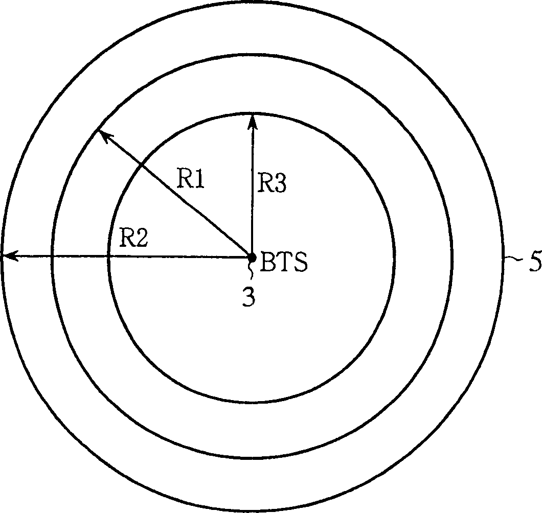
[0009] However, in the above-mentioned existing communication systems and communication methods, only the radius of a certain cell is reduced or expanded, so there is a problem of uneven distribution of interference and traffic in multiple cells.
In addition, there is a problem that the mobile terminal devices 4 do not necessarily exist concentrically with BTS 3 as the center, so it is not sufficient to control the traffic based on the control power for adjusting the cell radius as in the past.

Method used


Image

  • Communication system and communication method
  • Communication system and communication method
  • Communication system and communication method

Examples


Embodiment approach 1

[0049] Figure 4 Shows the cell structure diagram of the communication system in Embodiment 1 of the present invention, in which 11 is a BTS (base station) connected to the RNC (radio network controller), and 12 is composed of 6 sectors (multiple wireless areas) managed by BTS 11 district.

[0050] Figure 5 A block diagram showing the composition of the BTS 11 of the communication system in Embodiment 1 of the present invention. In the figure, 13 is six transceivers corresponding to each sector (sector 1 to sector 6) of the cell 12, and 14 is corresponding to each transceiver 13 6 power computing units (power control units), 15 is a power control unit (centralized control unit) connected to each power computing unit 14, and a to d are inside the BTS11 and between the BTS11 and the RNC (not shown). sent and received signals. Image 6 yes means Figure 5 In the block diagram of the structure of the middle power calculation unit 14, 16 is a comparator, 17 is a correction amo...

Embodiment approach 2

[0069] Figure 8 In order to show the communication system diagram of Embodiment 2 of this invention, in the figure, 19 is RNC (centralized control unit), and 20 is 3 BTS (power control unit) connected with RNC19. Each BTS 20 performs wireless communication with mobile terminal devices in the corresponding cells 1, 2, and 3 (plurality of wireless areas). Figure 9 yes Figure 8 In the power calculation part in the RNC19, in the figure, 21 is a power calculation part, 22 is a comparator, 23 is a correction amount calculator, and 24 is an adder. g to m1, 2, and 3 are signals transmitted and received within the RNC 19 and between the RNC 19 and each BTS 20 .

[0070] The operation will be described below.

[0071] A power instruction signal g of CPICH transmission power and a reference instruction signal h composed of a reference SIR and a reference RACH number are sent to the RNC 19 from the higher level of the RNC 19 . That is, the control commands set by the upper level ar...


PUM


Abstract

When a mobile terminal communicates by radio with another mobile terminal in a corresponding sector, a power calculating unit of a communication system controls the transmission power to the mobile terminal accessing a task according to a control command. A power control unit issues a control command to power calculating units to control all the transmission powers to the mobile terminals in sectors at a time. Thus the interference in a cell composed of sectors is reduced and the uneven traffic is solved when a mobile terminal communicates by radio with another mobile terminal in each sector.

Description

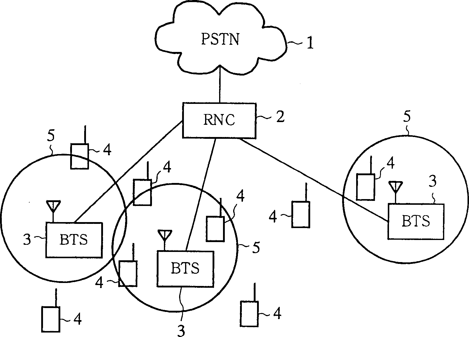
technical field [0001] The present invention relates to a communication system and a communication method, in particular to the control of transmission power. Background technique [0002] figure 1 Represents a part of the structure in the CDMA (Code Division Multiple Access) communication system, 1 is PSTN (public switched telephone network), 2 is the RNC (radio network control device) connected with PSTN1, 3 is a plurality of BTSs connected with RNC2 ( Base station), 4 is the mobile terminal equipment for wireless communication with BTS3, and 5 is the range that can communicate with BTS3, that is, the cell. [0003] The action is explained below. [0004] If utilize the transmission power of the downlink of any sub-district 5, wireless communication can input, call (visit) the telephone number of any one mobile terminal 4 users, corresponding to BTS3 of its sub-district 5, will respond to its call, and receive the call from its mobile terminal. The wireless signal of th...

Claims


Application Information

Patent Timeline
Patent Type & Authority Patents(China)
IPC IPC(8): H04B7/26H04B7/005H04W52/34H04W52/42
CPCH04W52/343H04W52/42
Inventor 吉村武浩
Owner MITSUBISHI ELECTRIC CORP
Why Eureka
Try Eureka