Multi-loop detector
A multi-circuit and measuring device technology, applied to instruments, circuits, inductors, etc., can solve problems such as poor operability
- Summary
- Abstract
- Description
- Claims
- Application Information
AI Technical Summary
Problems solved by technology
Method used
Image

Examples
Embodiment 1
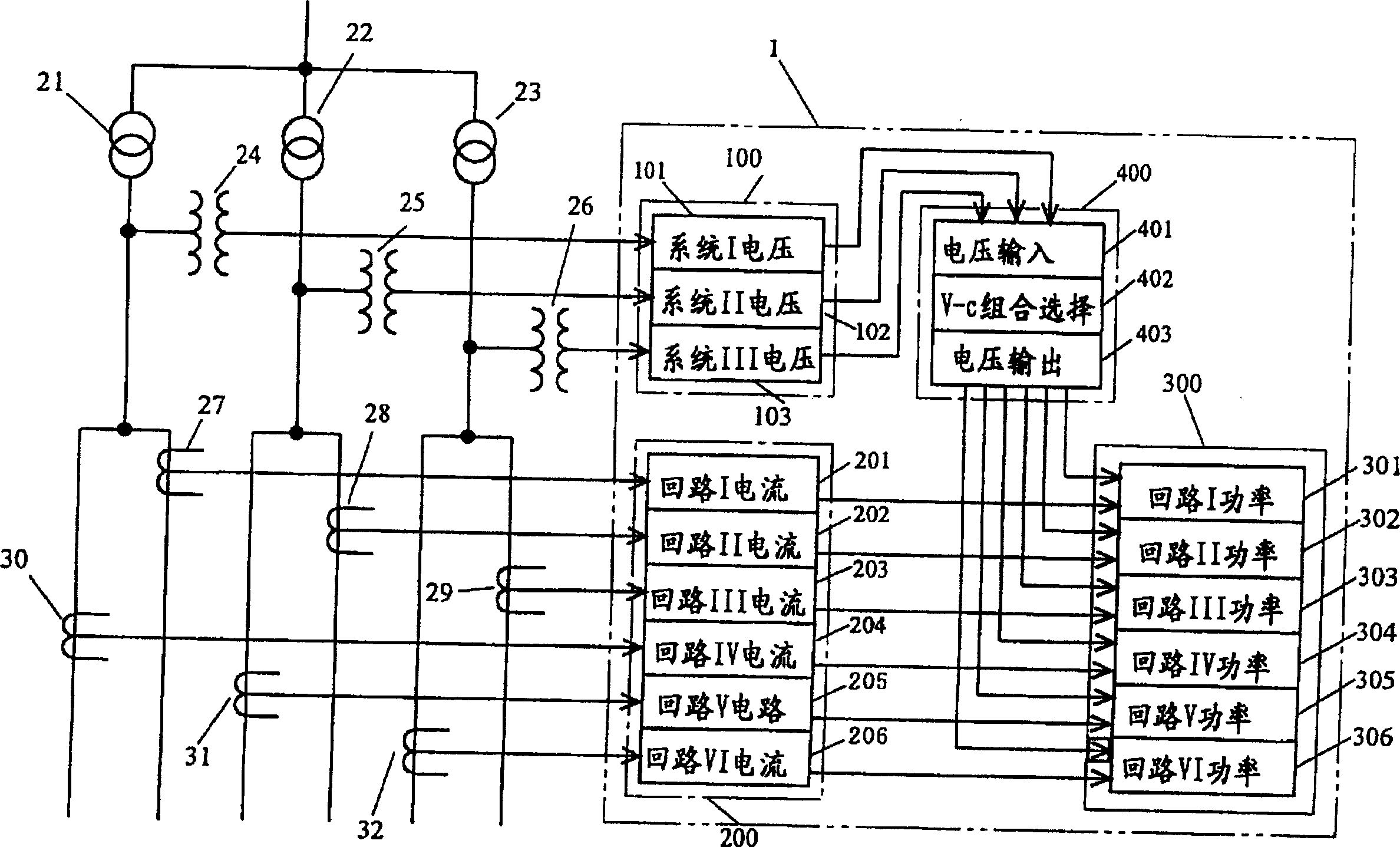
[0106] First, when the number of branches of each voltage system (the number of branch current loops) is not constant, use figure 1 and image 3 A multi-circuit type electric quantity measuring device that can effectively utilize the number of circuits for measurement will be described. figure 1 Indicates the case where the multi-circuit measuring device is a power meter, image 3 Indicates the case where the multi-circuit type measuring device is a watt-hour meter.
[0107] exist figure 1 Among them, 21, 22 and 23 are step-down transformers, which step down the voltage from the primary side to the secondary side voltage, and 24, 25 and 26 are instrument transformers called PTs. 27 to 32 are current transformers for converting the current value of each circuit into a current value for measurement. This embodiment relates to a multi-circuit type wattmeter that measures the power of each circuit from the system voltages and circuit currents of the power circuits configure...
Embodiment 2
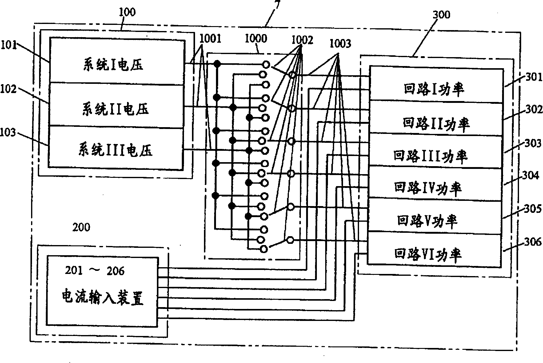
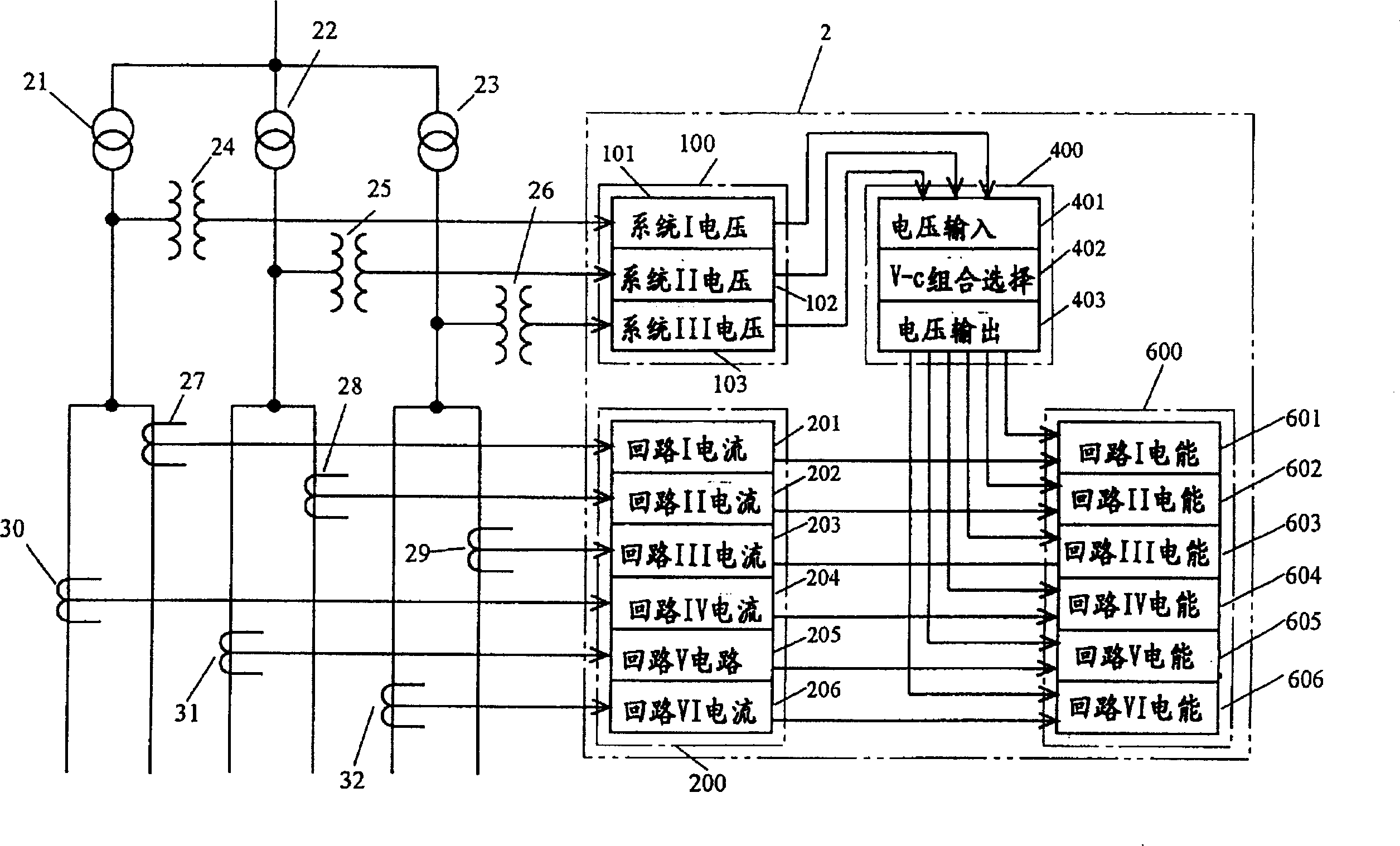
[0116] use below image 3 The case where the multi-circuit electric power quantity measuring device is a watt-hour meter will be described. exist image 3 In , the 2 surrounded by two dotted lines indicates a multi-circuit type watt-hour meter. The multi-circuit watt-hour meter 2 is composed of a voltage input device 100 , a current input device 200 , a current-voltage random combination device 400 and an electric energy metering device 600 . The voltage input device 100 is configured to correspond to three-system voltage input of system I voltage 101 to system III voltage 103 , and the current input device 200 is configured to correspond to six-circuit current input of circuit I current 201 to circuit VI current 206 . The electric energy metering device 600 is constituted by the same number of electric energy meters 601 to 606 as the number of electric current inputs of the electric current input device 200 .
[0117] The current-voltage arbitrary combination device 400 ta...
Embodiment 3
[0124] Figure 5 Indicates another specific configuration of a multi-circuit type wattmeter. exist Figure 5 Among them, 310 is a power measuring device, which samples the instantaneous values of voltage and current at the same time, and calculates by the product of the instantaneous values of voltage and current, the sum of the products within one sampling period, and the average of the sum during one sampling period power. Figure 5 The shown multi-circuit wattmeter is composed of a voltage input device 100 , a current input device 200 , a current switching device 500 , a current-voltage arbitrary combination device 400 , and a power measurement device 310 . The power measurement device 310 is composed of a time-division measurement device 311 composed of a sample and hold unit 3111 and an A / D converter 3112 , and a power calculation unit 312 composed of a calculation unit 3121 and a memory unit 3122 .
[0125] exist Figure 5 In the power measuring device 310, the v...
PUM
 Abstract
Description
Claims
Application Information
 - R&D Engineer
- R&D Manager
- IP Professional
- Industry Leading Data Capabilities
- Powerful AI technology
- Patent DNA Extraction
Browse by: Latest US Patents, China's latest patents, Technical Efficacy Thesaurus, Application Domain, Technology Topic.
© 2024 PatSnap. All rights reserved.Legal|Privacy policy|Modern Slavery Act Transparency Statement|Sitemap