

Fluorescent lamp producing method
A manufacturing method and technology for fluorescent lamps, which are applied in the manufacture of discharge tubes/lamps, tube/lamp screens, cold cathodes, etc., can solve the problems of increased process loss, complex manufacturing process, process loss and the like
Inactive Publication Date: 2006-04-12
PANASONIC CORP
View PDF2 Cites 0 Cited by
- Summary
- Abstract
- Description
- Claims
- Application Information
AI Technical Summary
Problems solved by technology
[0004] However, the manufacturing method of the above-mentioned conventional fluorescent lamp has such a problem: the former needs the process of fixing the lead wire with glass beads before the electrode is mounted on the lead wire, and the assembled body and the exhaust pipe must be clamped and sealed when the glass tube is clamped and sealed. If the lead wires are held separately, the loss of man-hours and materials is also large, and the manufacturing process becomes complicated.
[0005] On the other hand, the latter has the problem of weak fixing force because the part of the electrode body before the fixing bead is installed is fixed with a magnet on only one side, and the electrode wire body falls off before the fixing bead is inserted, which increases the process loss.
In addition, a support mechanism for clamping and sealing the assembly of the electrode wires to the glass tube is required, which leads to a problem of complicated processes.
There is also such a problem that in order to exhaust gas at the open end of the side of the glass tube that is not clamped and sealed, it must be connected to another small-diameter exhaust tube, etc., resulting in material loss and process loss.
Method used
View moreImage
Smart ImageViewing Examples

Examples
Embodiment 1
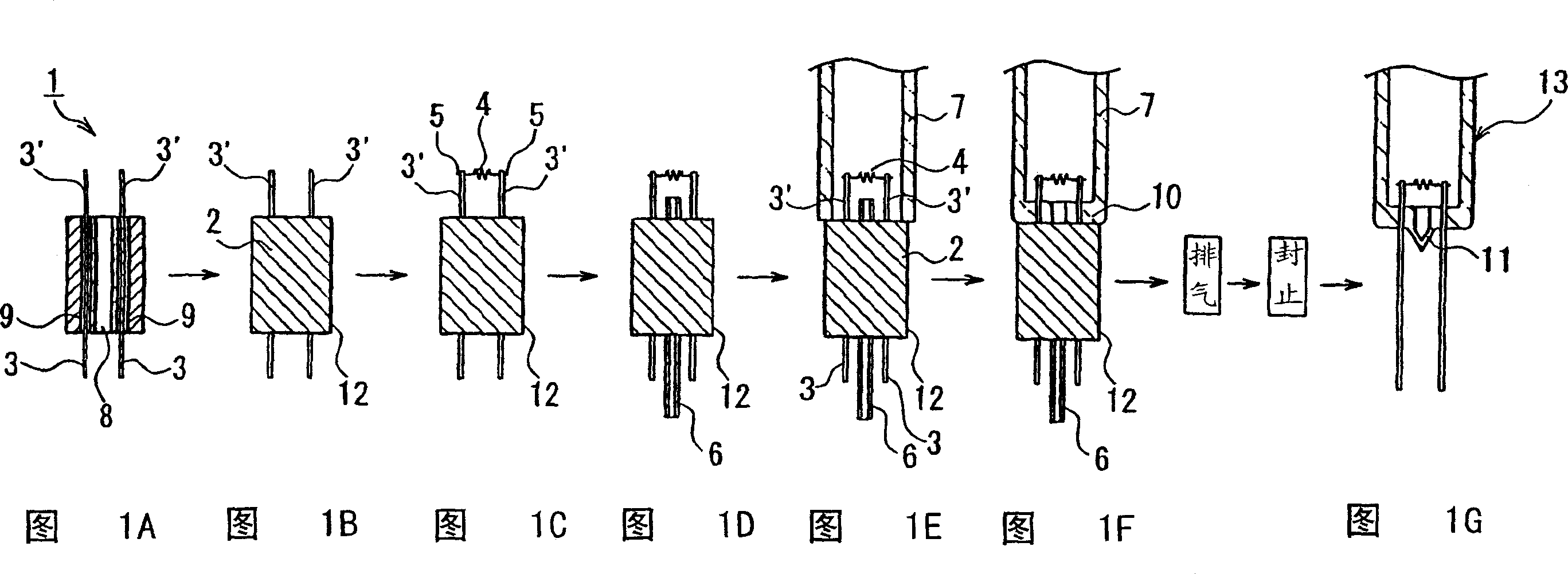
[0038] When connecting two glass tubes with a tube outer diameter of 15.5 mm, a wall thickness of 0.8 mm, and a total length of 180 mm in a bridge type to make a W-shaped compact fluorescent lamp 13 of a discharge circuit, follow the steps of Fig. 1A-Fig. 1G and A fluorescent lamp was produced as described above. The cross-sectional view of the fabricated fluorescent tube is shown in Figure 4 shown.
[0039] Before FIG. 1E , 8 mg of zinc-amalgam as a mercury-releasing alloy and 10 mg of indium-bismuth alloy as an amalgam substance were sealed in the glass tube 7 .
Login to View More PUM
 Abstract
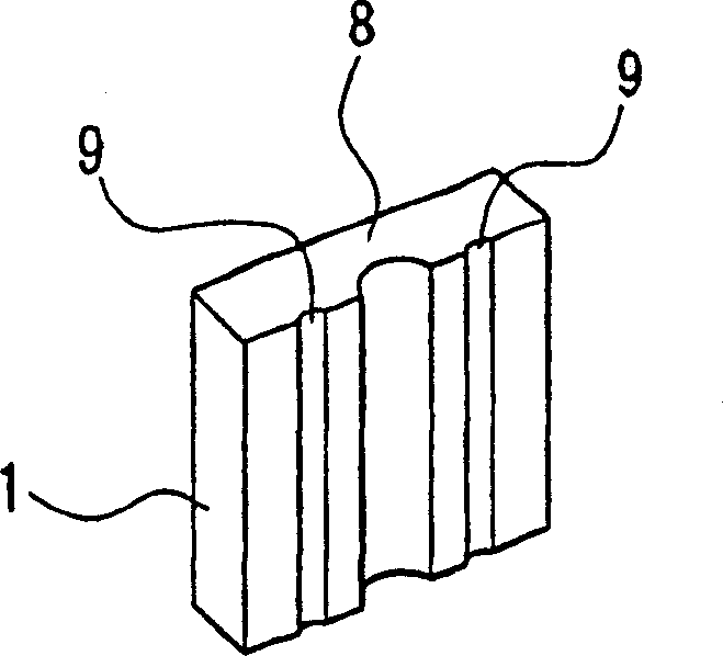
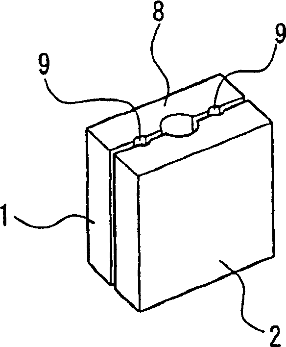
A fluorescent lamp is produced by substantially parallelly disposing, holding and fixing a pair of lead wires (3, 3) between a block-like holder and a block-like auxiliary holder (2), attaching an electrode (4) to the tips (3', 3') of the projecting lead wires (3, 3), disposing an exhaust pipe (6) with its opposite ends positioned outside an exhaust pipe receiving groove, inserting the electrode (4) and exhaust pipe (6) into the end of a glass tube (7), heating the glass tube adjacent its end to effect the heat pinch seal of the lead wires, thus integrating the glass tube and exhaust pipe, evacuating the glass tube through the exhaust pipe, removing the block-like holder and block-like auxiliary holder, heat-sealing the tip of the glass tube , and cutting away the exhaust pipe. It is possible to provide a fluorescent lamp producing method that is simple, reliable and stable, with nothing but the electrode existing between the lead wires.
Description
technical field [0001] The present invention relates to a method for manufacturing a fluorescent lamp, and more specifically, to a fluorescent lamp in which no fixed beads (glass beads) are provided on the lead wires in the fluorescent lamp, and the exhaust can be continuously performed from the holding of the lead wires to the glass tube with a specific jig method of manufacturing fluorescent lamps. Background technique [0002] Conventionally, there is a well-known method of manufacturing a stemless fluorescent lamp as a method of omitting a stem for assembling electrodes to reduce material costs and effectively utilize the length of a luminous body. For example, JP-A-6-290735 discloses a manufacturing method in which a pair of lead wires are fixed with glass beads to mount electrodes, and the lead wires are clamped and sealed to the end of the glass tube. Moreover, such a method is also known, that is, after a pair of slender electrode wires are fixed with magnets, the t...
Claims
Login to View More Application Information
Patent Timeline
 Patent Type & AuthorityPatents(China)
IPC IPC(8): H01J9/26H01J9/32H01J9/00H01J9/04H01J9/06H01J9/20H01J9/40
CPCH01J9/326H01J9/04H01J9/06H01J9/40
Inventor小林员正须藤和好武内正广正保泉
OwnerPANASONIC CORP