Method and device forr emphasizing pitch
A technology that enhances the device and tone, and is applied in speech analysis, speech recognition, instruments, etc., and can solve problems such as deterioration of speech naturalness and sensory quality
- Summary
- Abstract
- Description
- Claims
- Application Information
AI Technical Summary
Problems solved by technology
Method used
Image

Examples
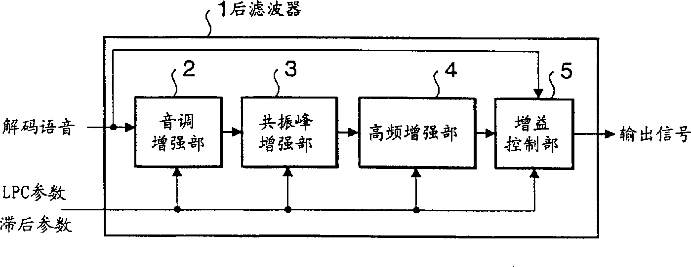
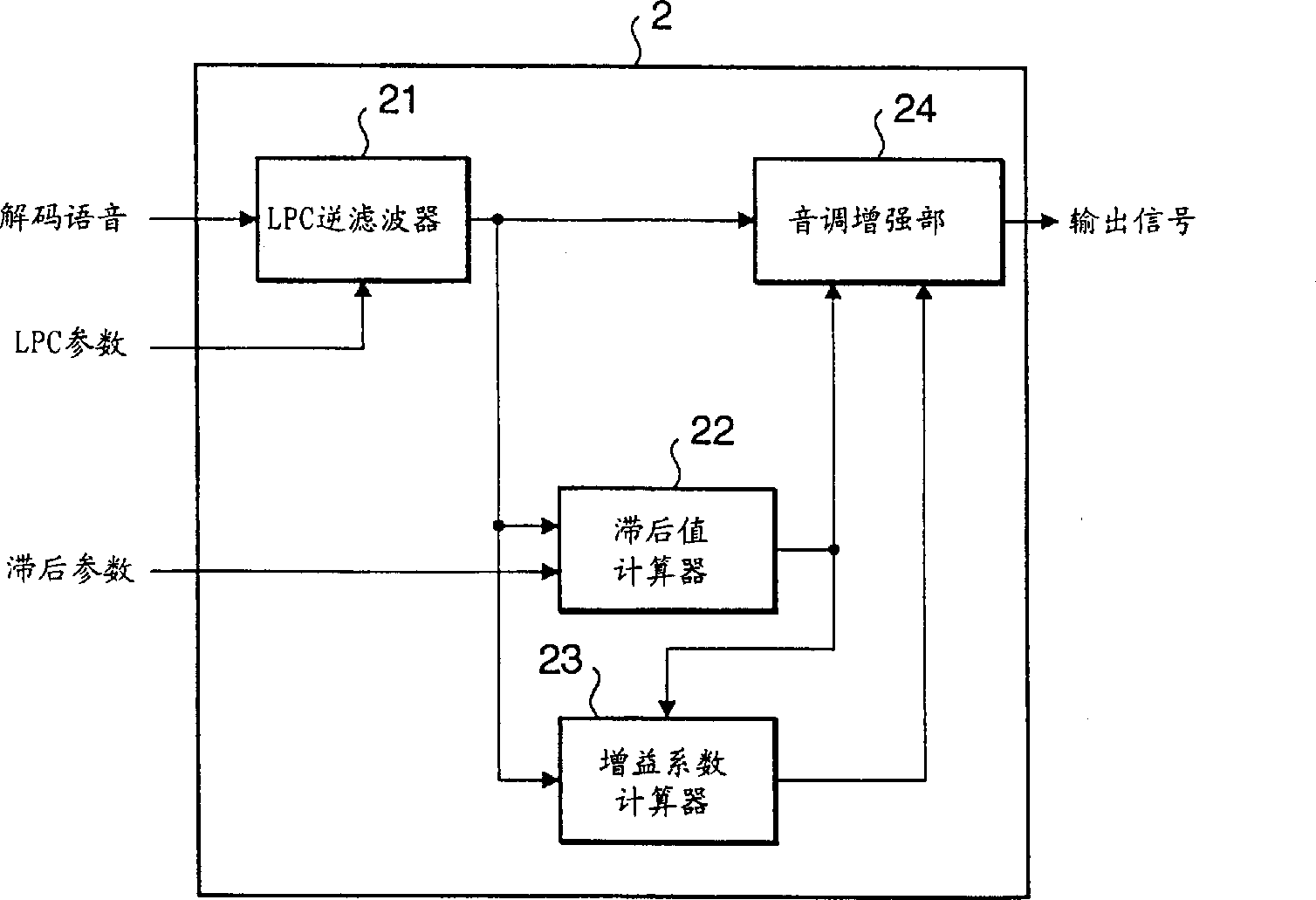
Embodiment 1
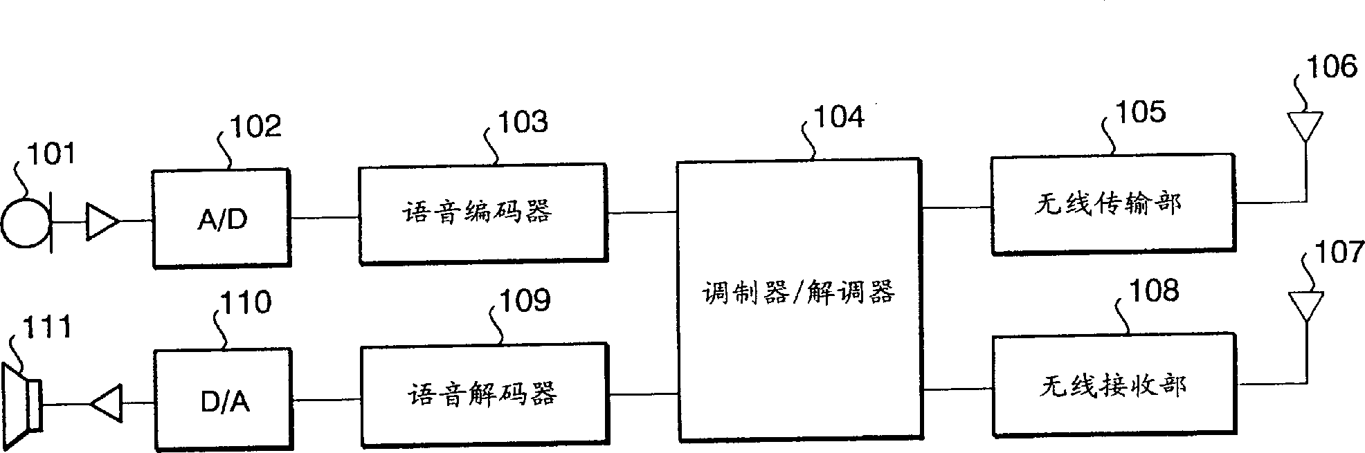
[0024] image 3 It is a structural block diagram of a wireless communication device equipped with a post-filter according to Embodiment 1 of the present invention.
[0025] In this wireless communication device, a transmitting end converts voice into an electrical analog signal through a voice input device 101 such as a microphone, and outputs it to an A / D converter 102 . The analog voice signal is converted into a digital voice signal by the A / D converter 102 and output to the voice encoder 103 . Speech coder 103 speech codes the digital voice signal, and outputs coded information to modulator / demodulator 104 . The modulator / demodulator 104 digitally modulates the coded voice signal, and sends it to the wireless transmission section 105 . The wireless transmission unit 105 performs predetermined wireless transmission processing on the modulated signal. This signal is sent via antenna 106 .
[0026] On the other hand, on the receiving side of the wireless communication dev...
Embodiment 2
[0050] Figure 7 It is a functional block diagram of the pitch enhancement part of the post-filter of Embodiment 2 of the present invention. The post-filter of Embodiment 2 uses the residual signal output by the LPC inverse filter instead of the decoded speech signal as the input of the pitch weighting filter 105 . The rest of the structure is the same as in Embodiment 1.
[0051] Embodiment 2 performs pitch enhancement using the residual signal and gain coefficients with first and second lag values. Here, it uses, as the filter characteristic of the LPC inverse filter 101, the characteristic corresponding to the numerator term of the formant enhancement filter shown in Equation (9) performed in the subsequent stage of the pitch enhancement process. Wherein, ai (i=1, . . . , Np) is the LPC coefficient, γn and γd are constants controlling the degree of formant enhancement, and 1 / gf is a gain compensation term. H f ( ...
PUM
 Abstract
Description
Claims
Application Information
 - R&D
- Intellectual Property
- Life Sciences
- Materials
- Tech Scout
- Unparalleled Data Quality
- Higher Quality Content
- 60% Fewer Hallucinations
Browse by: Latest US Patents, China's latest patents, Technical Efficacy Thesaurus, Application Domain, Technology Topic, Popular Technical Reports.
© 2025 PatSnap. All rights reserved.Legal|Privacy policy|Modern Slavery Act Transparency Statement|Sitemap|About US| Contact US: help@patsnap.com