Magnetic support electrical drive device

A technology of electric drive and magnetic support, applied to synchronous motors with stationary armatures and rotating magnets, electric components, bearings, etc., can solve the problem of large number of coils, and achieve the effect of high attenuation and increased stability range

Inactive Publication Date: 2006-06-07
LEVITRONIX TECH
View PDF2 Cites 0 Cited by
  • Summary
  • Abstract
  • Description
  • Claims
  • Application Information

AI Technical Summary

Problems solved by technology

But the disadvantage is that the two field windings bring a large number of coils

Method used


Image

  • Magnetic support electrical drive device
  • Magnetic support electrical drive device
  • Magnetic support electrical drive device

Examples


Embodiment Construction

[0039] The following examples illustrate possible embodiments of the invention.

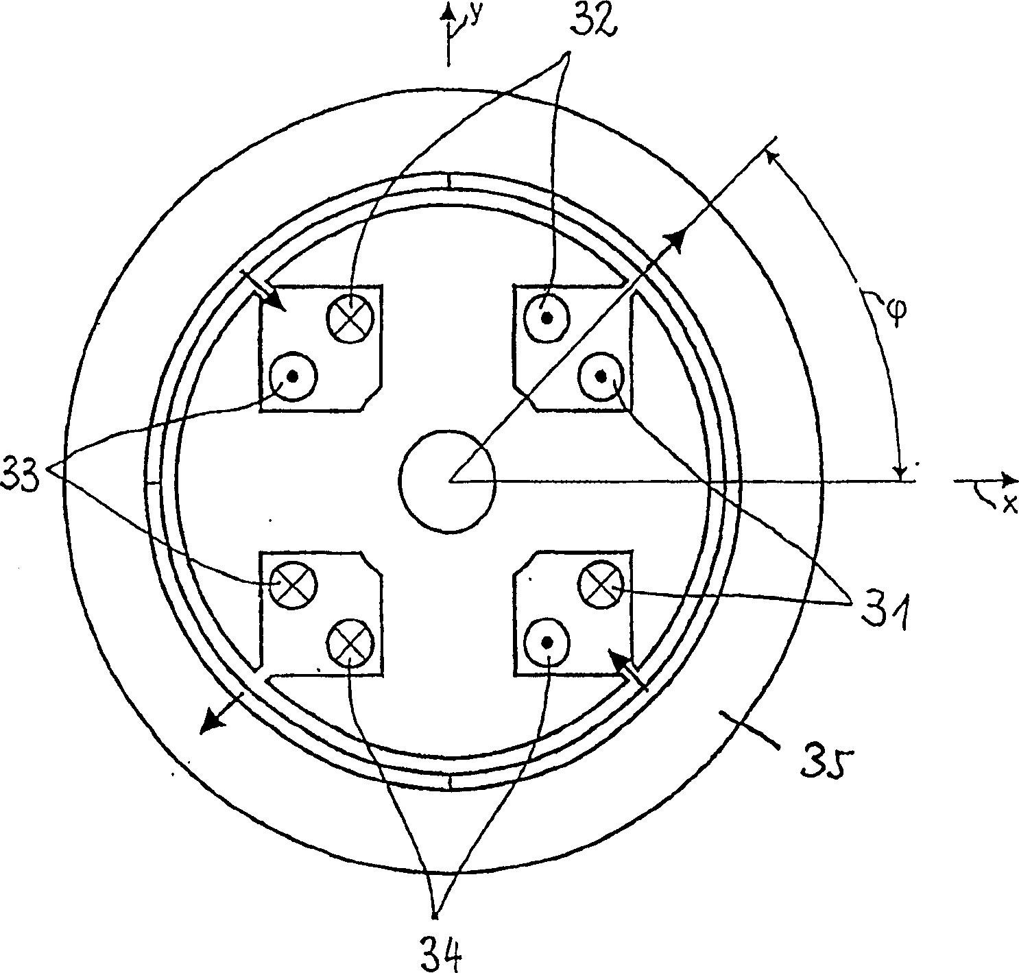
[0040] Figure 4A motor with 5 concentrated individual coils 41 , 42 , 43 , 44 , 45 is shown. With this stator arrangement, usually with superimposed current components flowing through the coils, both a bipolar rotating magnetic field and a quadrupole magnetic field or two bipolar and quadrupole magnetic potentials can be obtained simultaneously. Therefore, on a two-pole rotor, a torque can be obtained by cooperating with the two-pole winding magnetic potential, and a radial supporting force can be obtained by cooperating with the four-pole winding magnetic potential.

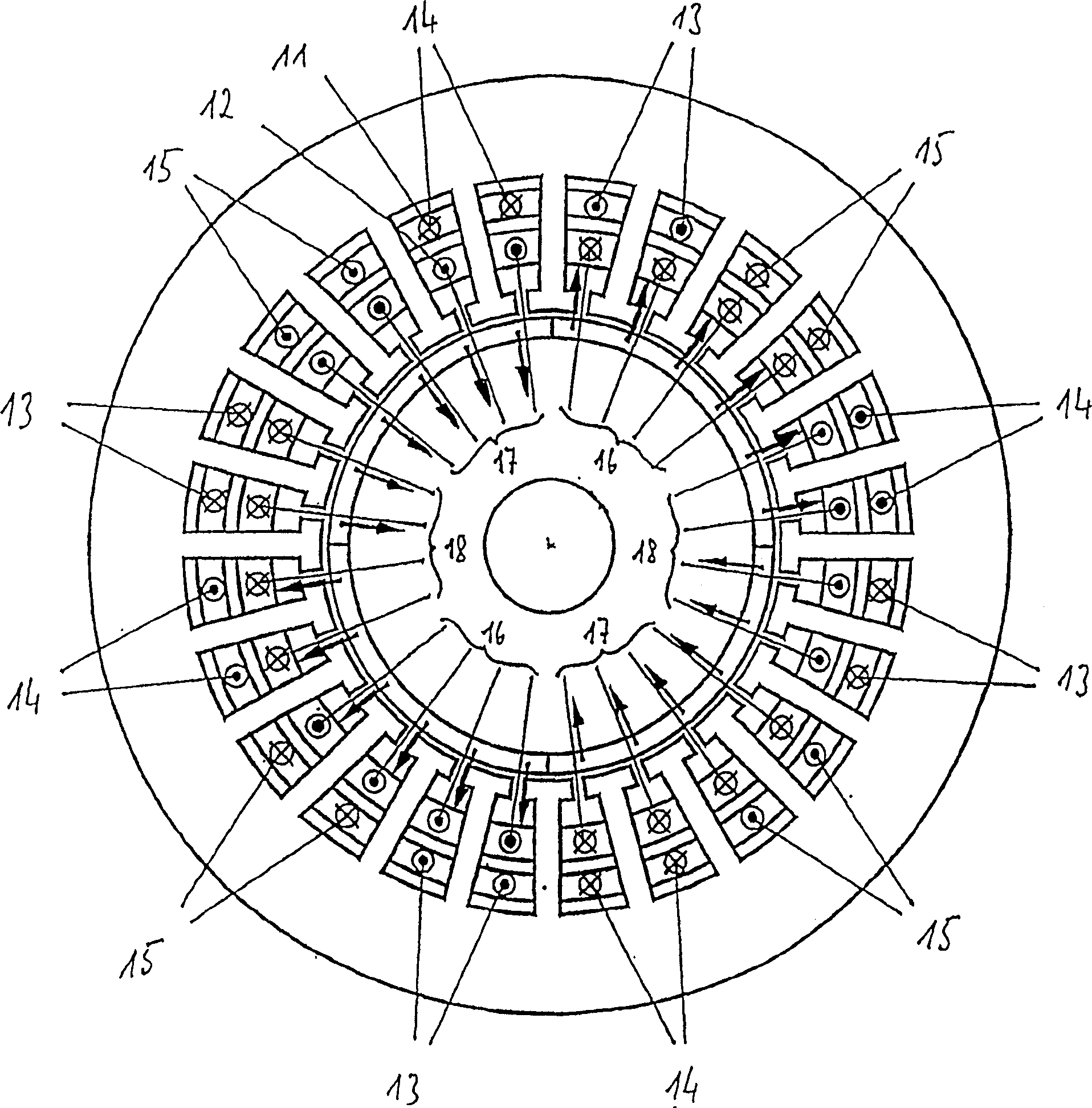
[0041] An odd number of coils or cores not divisible by the two pole numbers 4 and 2 used results in an asymmetrical core cross-section and an asymmetrical magnetic potential distribution or field distribution in the area of ​​the stator or air gap.

[0042] Therefore, the coil current is determined according to the angular posi...


PUM


Abstract

The invention relates to an economical, non-wearing, electrical permanent magnet drive for actively controlling the rotor position in three degree of freedom. The stator windings produce superimposed fields with different pole numbers in the pole pitches by unsymmetrical magnetomotive force distributions.

Description

technical field [0001] The invention relates to a magnetically supported electric drive system which is inexpensive and wear-free. Background technique [0002] Magnetic bearing technology has opened up a wide range of application fields for machinery manufacturing and instrument manufacturing because of its extremely high requirements for the range of revolutions, life, cleanliness, and sealing of the transmission system—that is, it has opened up a wide range of applications in the use of conventional bearing technology. Applications that are impossible or difficult to achieve. For example, high-speed milling and grinding machine spindles, turbo compressors, vacuum pumps or pumps for high-purity chemical or pharmaceutical products are already equipped with magnetic bearings. [0003] The machine cross-sections in the following figures are shown only as examples and some of them are greatly simplified and are only used for a more detailed illustration of the functional prin...

Claims


Application Information

Patent Timeline
Patent Type & Authority Patents(China)
IPC IPC(8): H02K7/09H02K21/02H02K3/18F16C39/06H02K21/12
CPCF16C32/0493H02K7/09F16C2380/26H02K3/12
Inventor 沃尔夫冈·阿姆莱恩西格弗里德·西尔伯
Owner LEVITRONIX TECH
Why Eureka
Try Eureka