Feed horn structure and its manufacturing method, frequency transformer and satellite communication receiving antenna

A technology of feeding horn and satellite communication, applied in the field of satellite communication receiving antenna, can solve the problems of breakage, cooperating force damage, cost increase, etc.

Inactive Publication Date: 2006-08-02
SHARP KK
View PDF3 Cites 1 Cited by
  • Summary
  • Abstract
  • Description
  • Claims
  • Application Information

AI Technical Summary

Problems solved by technology

[0004] According to the combination method above, the balance of the mating force may be disrupted, resulting in whitening or breakage near the buckle of the horn cap.
In addition, since the O-ring 104 is used to maintain airtightness, the cost also increases

Method used


Image

  • Feed horn structure and its manufacturing method, frequency transformer and satellite communication receiving antenna
  • Feed horn structure and its manufacturing method, frequency transformer and satellite communication receiving antenna
  • Feed horn structure and its manufacturing method, frequency transformer and satellite communication receiving antenna

Examples


no. 1 example

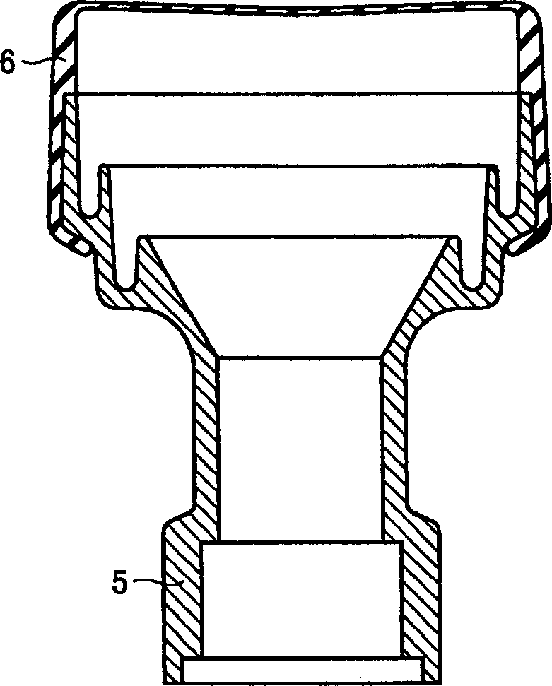
[0044] figure 1 is a front view showing a vertical section of the feed horn structure according to the first embodiment of the present invention. The horn cap 6 and the die-cast feed horn 5 are integrated together by integral molding. Therefore, it is not necessary to use a buckle to mount the horn cap to the feed horn in the manufacturing step, so that whitening, breakage, etc. do not occur. Accordingly, manufactured products are improved, and manufacturing costs are reduced. Also, an expensive O-ring for maintaining airtightness can be eliminated, so cost reduction can be achieved.

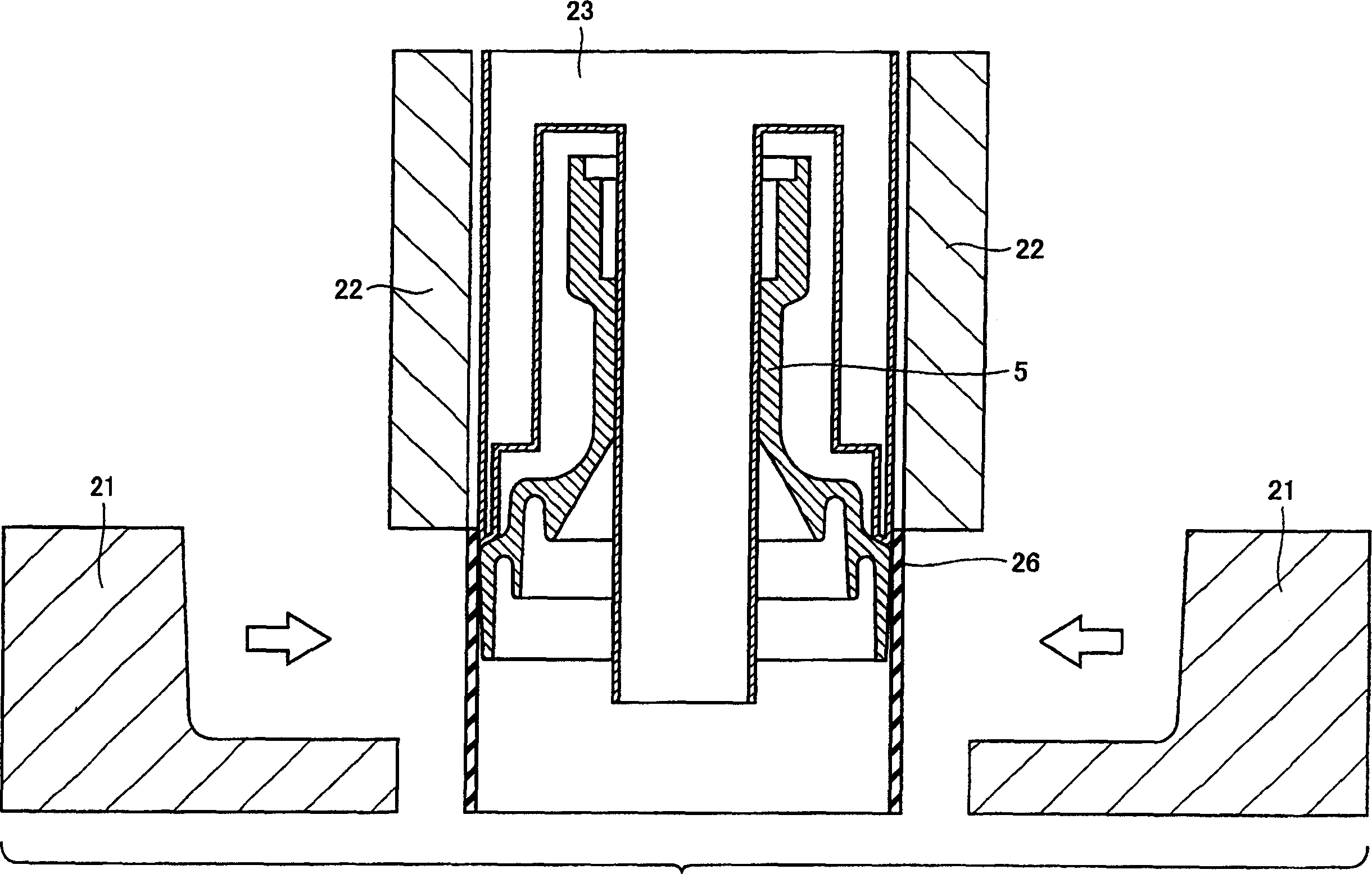
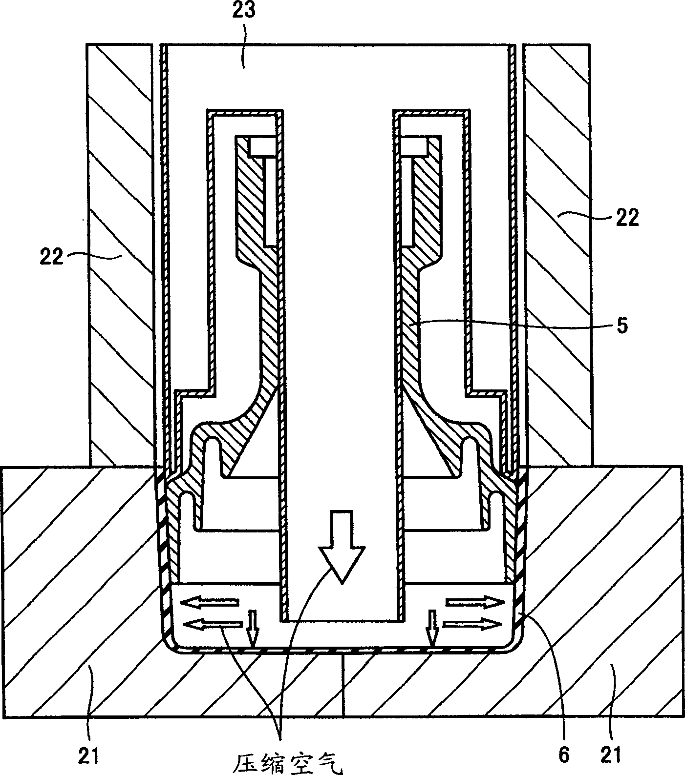
[0045] Next, will describe figure 1 The fabrication method of the feed horn structure shown. First, if figure 2 Feed horn 5 is mounted to blow molds 22 and 23 as shown. Then, the molded parison 26 of resin material is fitted to a port of the feed horn, and is compressed with the blow mold 21 . Thereafter, if image 3 As shown, compressed air is blown in so that the horn cap 6 is shape...

no. 2 example

[0047] Figure 4 is a front view showing a vertical cross-section of the feed horn structure according to the second embodiment of the present invention. Figure 5 According to the feed horn structure of the second embodiment of the present invention, along Figure 4 A horizontal cross-sectional view of the V-V line. In the above feed horn structure, in order to prevent the rotational displacement of the horn cap 6 relative to the feed horn 5, a protruding portion 7 is provided on the feed horn 5, and a concave portion is provided on the horn cap 6, so that Compatible with protrusions.

[0048] Figure 6 is a front view showing a vertical cross-section of the feed horn structure according to a modification of the second embodiment of the present invention. Figure 7 According to the feed horn structure of the modification of the second embodiment of the present invention, along Figure 6 Horizontal section view of line VII-VII. In this feed horn structure, with Figure ...

no. 3 example

[0051] Figure 8 is a front view showing a vertical section of a structure of a feed horn according to a third embodiment of the present invention. The feed horn structure of the third embodiment is characterized in that it includes a feed horn 5 formed by molding a feed horn shape with a waterproof resin 9 and providing a plating layer 10 on its inner surface. With the above feed horn, the structure of the feed horn can be integrated, and its weight can also be reduced.

[0052] Figure 9 is a front view showing a vertical cross-section of the feed horn structure according to a modification of the third embodiment of the present invention. In a modification of the third embodiment, the feed horn 5 is formed by forming a feed horn shape with a general-purpose resin and covering its entirety with a plating layer 12 . The horn cap 13 is formed to cover the periphery of the feed horn. pass Figure 9 The variant shown, can provide a comparison to Figure 8 The feed horn stru...


PUM


Abstract

A feed horn structure in which a feed horn and a horn cap can be combined without generating whitening, crack and the like, a manufacturing method thereof, a converter having that feed horn structure, and a satellite communication receiving antenna can be obtained. The feed horn structure of a satellite communication receiving converter includes a cylindrical feed horn (5) receiving a radio wave from an antenna portion and guiding the radio wave, and a horn cap (6) fixed to the feed horn so as to surround one end of the feed horn at antenna side. The feed horn and the horn cap are integrated by integral molding.

Description

technical field [0001] The present invention relates to a feeder horn structure for receiving satellite communication (specifically, satellite broadcasting), a manufacturing method thereof, a frequency converter with a feeder horn structure, and a satellite communication receiving antenna. Background technique [0002] Figure 11 It is a perspective view of a satellite broadcast receiving antenna. Radio waves from the satellite are reflected at the parabolic antenna 150, enter the feed horn 101, and are guided. The radio wave guided in this way is converted into a television signal or an audio signal by the frequency converter 140 connected to the feed speaker 101 (for example, Japanese Patent Laid-Open No. 7-38321, Japanese Patent Laid-Open No. 9-46102, Japanese Utility Model Publication No. 6-81120). [0003] Figure 12 is a front view of the feed horn structure with horn caps in a conventional LNB (Low Noise Block) downconverter, showing their vertical section. Figur...

Claims


Application Information

Patent Timeline
Patent Type & Authority Patents(China)
IPC IPC(8): H01Q1/42H01Q13/02F16L27/10
Inventor 广田诚须贺博之
Owner SHARP KK
Why Eureka
Try Eureka