Electric transmission device for means of transportation

A transportation tool and electric transmission technology, which is applied in transmission devices, electric power devices, gear transmission devices, etc., can solve the problem of small deceleration and achieve the effect of small space, high power density, and compact structure

Inactive Publication Date: 2006-08-30
奥斯卡・瓦绍尔
View PDF13 Cites 2 Cited by
  • Summary
  • Abstract
  • Description
  • Claims
  • Application Information

AI Technical Summary

Problems solved by technology

For this reason and the small reduction between the motor part and the drive gear, the application of this combination to a traction drive is problematic

Method used


Image

  • Electric transmission device for means of transportation
  • Electric transmission device for means of transportation
  • Electric transmission device for means of transportation

Examples


Embodiment Construction

[0028] In the introduction it is to be kept in mind that in the various embodiments the same parts have the same reference symbols and part names, where the disclosure throughout the specification can be referred to the same parts with the same reference symbols and part names. Furthermore, selected positional specifications such as top, bottom, side, etc. in the description refer to the right description and the shown figure, and when the position is changed, they are sensibly transferred to the new position. Furthermore, individual technical features or combinations of technical features formed from the different exemplary embodiments shown and described are shown for inventive individual solutions or solutions according to the invention.

[0029] Creative independent solutions to tasks can be reached from the instructions.

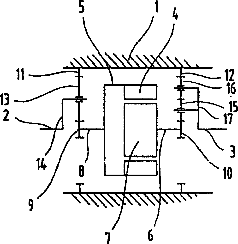
[0030] Such as figure 1 As shown, the electric transmission device is composed of a shell 1 that is fixed relative to the vehicle, and a first drive t...


PUM


Abstract

The invention relates to an electric drive for a vehicle. A housing (1) that is stationary in relation to the vehicle frame is provided. A motor housing (5) having a stator (4) and a rotor (7) being provided in said motor housing (5) are rotationally mounted in said housing. The motor housing and the rotor perform opposite rotational movements. A drive train (2) is connected to the motor housing and the rotational movement of the motor housing is carried out by means of a transmission device with the same drive and output direction of rotation. The remaining drive train is connected to the rotor and the rotational movement of the rotor is carried out by means of a transmission device with opposite drive and output direction of rotation. The transmission devices are planetary gears. The rotor engages with the planet wheels (13 or 16) of the allocated planetary gear by means of a spur pinion (10) that is arranged on the shaft or the motor housing engages with the planet wheels of the allocated planetary gear by means of a spur pinion that is connected to the motor housing and is arranged on the axis of the motor housing. A web (14 or 17) is provided. Said web is connected to the axles of the planet wheels of each planetary gear and drives the wheel shaft assigned thereto.

Description

technical field [0001] The invention relates to electric drives for vehicles. Background technique [0002] US Pat. No. 5,169,17 A describes an electric motor which is used to drive two gears independently of the rotational speed in such a way that one gear is rigidly connected to the field winding and the other is connected to the rotor via a differential gearing. To get the same torque on both gears, the differential gearing must only reverse the rotor steering without changing speed at the same speed of the field windings and rotor. In the variant shown, it is, on the one hand, in the form of a pair of ring gears similar to the construction in known shaft differentials, and on the other hand, in the form of a spur planetary transmission with the same function. [0003] Furthermore, US patent US613894A describes a direct current generator and electric motor for a vehicle. In the construction of the two coaxially rotatable motor parts, the two parts are connected to each ...

Claims


Application Information

Patent Timeline
Patent Type & Authority Patents(China)
IPC IPC(8): H02K16/02H02K7/116H02K23/60B60K1/00B60K17/04F16H1/28B60K17/16B60L15/20F16H3/44H02K16/00
CPCH02K7/116B60K17/046Y02T10/7258B60K1/00B60K17/16H02K23/60H02K16/005Y02T10/72
Inventor 奥斯卡·瓦绍尔
Owner 奥斯卡・瓦绍尔
Why Eureka
Try Eureka