Emulator equipment and correlation technique

A simulator and equipment technology, applied in the direction of instrument, computer-aided design, CAD circuit design, etc., can solve problems such as destruction

Inactive Publication Date: 2006-10-04
PANASONIC CORP
View PDF0 Cites 0 Cited by
  • Summary
  • Abstract
  • Description
  • Claims
  • Application Information

AI Technical Summary

Problems solved by technology

[0004] The problem is that as the system LSI becomes more complex and larger in size, it is necessary to prepare more of these functional models
As a result, this may destroy any benefit of co-design as the added processing steps offset or even outweigh the stated benefit

Method used


Image

  • Emulator equipment and correlation technique
  • Emulator equipment and correlation technique
  • Emulator equipment and correlation technique

Examples


Embodiment Construction

[0038] Hereinafter, preferred embodiments of the present invention will be described with reference to the accompanying drawings.

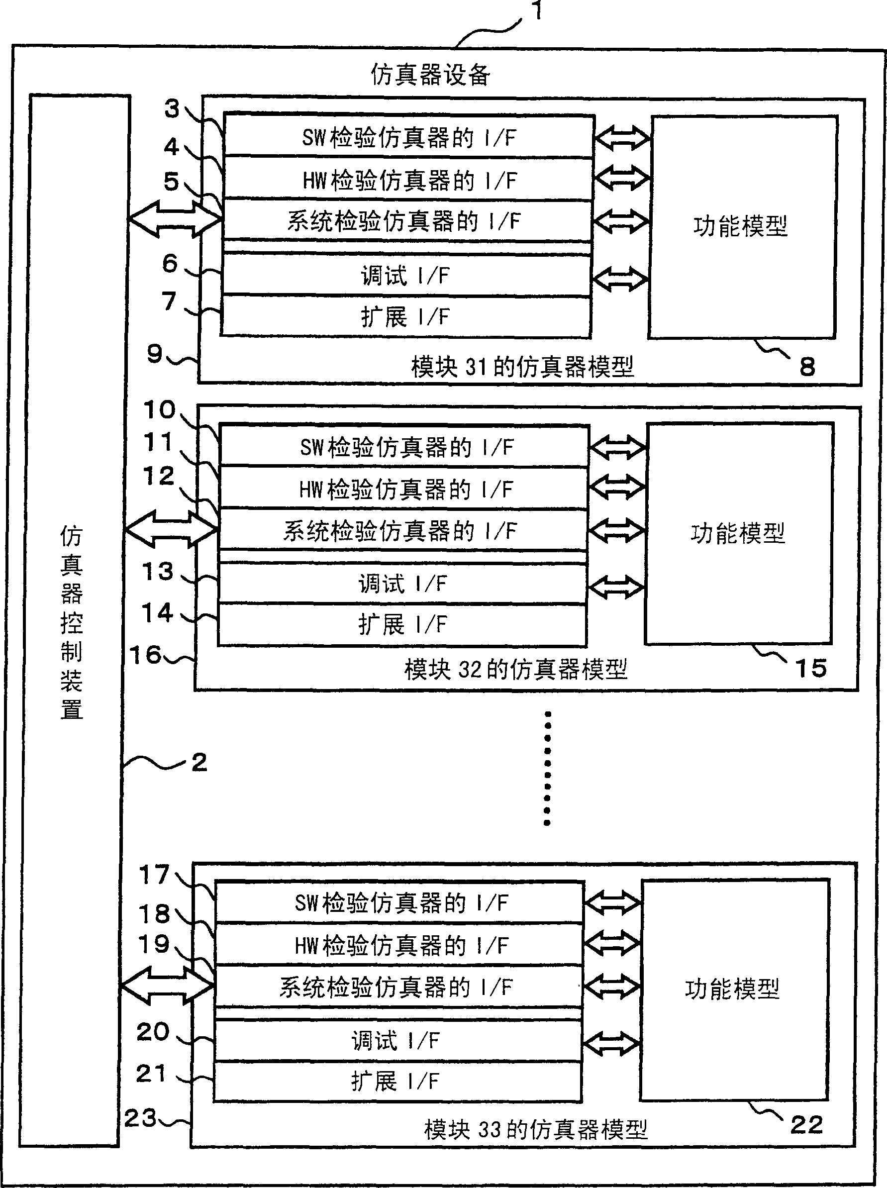
[0039] exist figure 1 In the simulator device 1 shown, a system including modules 31, 32, and 33 is a simulation object. The simulator device 1 comprises: the simulator model 9 of the module 31 including the function model 8 , the simulator model 16 of the module 32 including the function model 15 , and the simulator model 23 of the module 33 including the function model 22 . For example, module 31 is a CPU, and modules 32 and 33 are peripheral hardware.

[0040] The simulator model 9 includes an interface 3 for a simulator for checking software, an interface 4 for a simulator for checking hardware, an interface 5 for a simulator for checking a system, an interface 6 for debugging, and an interface for extension 7.

[0041] Likewise, the simulator model 16 includes an interface 10 for a simulator for testing software, an interface 11 for a simu...


PUM


Abstract

A simulator apparatus comprises a simulator model including a functional model for CPU constituting a system to be simulated and a simulator model including a functional model for hardware to be connected to buses linked to the CPU. The respective simulator models include plural types of interfaces. The plural types of the interfaces enable plural types of simulators for different uses to access the functional models. The simulator apparatus further comprises a simulator controlling device for selecting any of the plural types of the interfaces and accessing the respective functional models via the selected interfaces.

Description

technical field [0001] The present invention relates to a simulation technique for large-scale integration (LSI), and more particularly, to an improvement in a technique for efficiently verifying hardware, software, and systems in an upstream design stage of a chip-level system structure. Background technique [0002] In recent years, there has been an increasing demand for integrated circuits of monolithic structure, miniaturization, weight reduction, energy saving, and cost reduction. This trend is especially evident in the field of digital IT home appliances. In response to such demands, the semiconductor chip manufacturing industry has shifted its attention to system LSIs. [0003] If the system is divided into hardware and software so that the hardware and software are developed sequentially, development takes longer. Therefore, so-called "co-design" in which hardware and software are jointly developed at the same time is increasingly employed. In the case of co-desi...

Claims


Application Information

Patent Timeline
Patent Type & Authority Patents(China)
IPC IPC(8): G06F11/36G06F17/50G06G7/62
CPCG06F17/5022G06F30/33
Inventor 筱原克哉
Owner PANASONIC CORP
Why Eureka
Try Eureka