
Teaching aid for demonstrating dynamic relations of instant center, pole trace, temporary axis and pole face in fixed point rotation of rigid body

A technology of body pole track and rigid rotor, which is applied in the field of demonstration teaching aids and can solve the problem of not being able to demonstrate the dynamic relationship of three-dimensional space positions.

Inactive Publication Date: 2006-10-11
HARBIN INST OF TECH AT WEIHAI
View PDF0 Cites 0 Cited by
  • Summary
  • Abstract
  • Description
  • Claims
  • Application Information

AI Technical Summary

Problems solved by technology

The "demonstration teaching aid for the dynamic relationship between the instantaneous center and pole of rigid body rotation" introduced in the second issue of "Physical Experiments" in 2001 can only demonstrate the two-dimensional dynamic relationship between the instantaneous center and pole when the rigid body moves in parallel in the plane, but cannot demonstrate the fixed-point rotation of the rigid body The Dynamic Relationship Between Time-Instant Center and Pole in Three-Dimensional Space

Method used


Image

  • Teaching aid for demonstrating dynamic relations of instant center, pole trace, temporary axis and pole face in fixed point rotation of rigid body
  • Teaching aid for demonstrating dynamic relations of instant center, pole trace, temporary axis and pole face in fixed point rotation of rigid body
  • Teaching aid for demonstrating dynamic relations of instant center, pole trace, temporary axis and pole face in fixed point rotation of rigid body

Examples


specific Embodiment approach 1

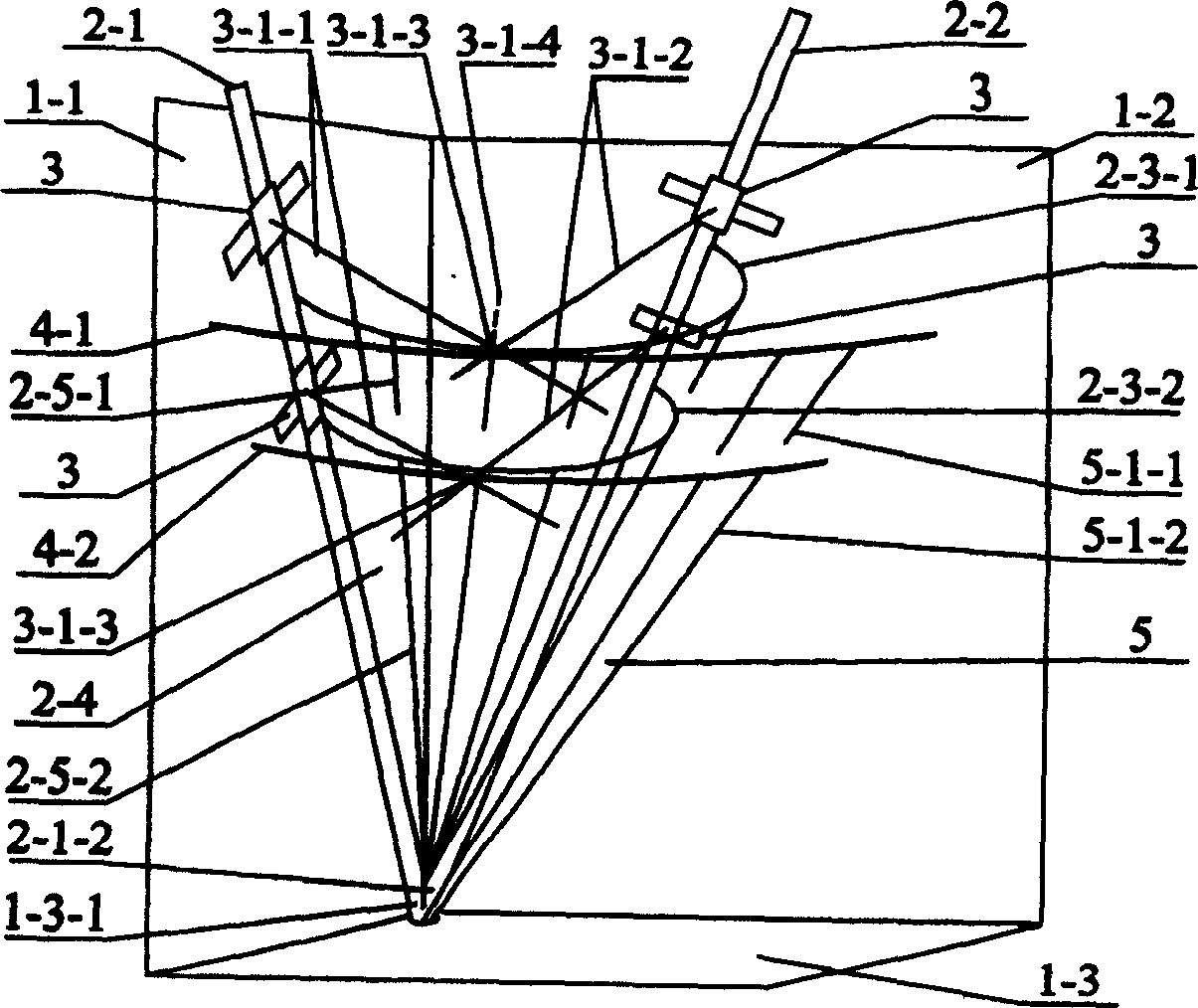
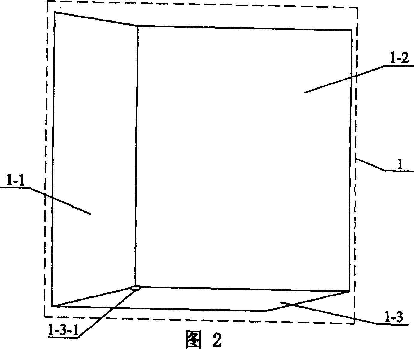
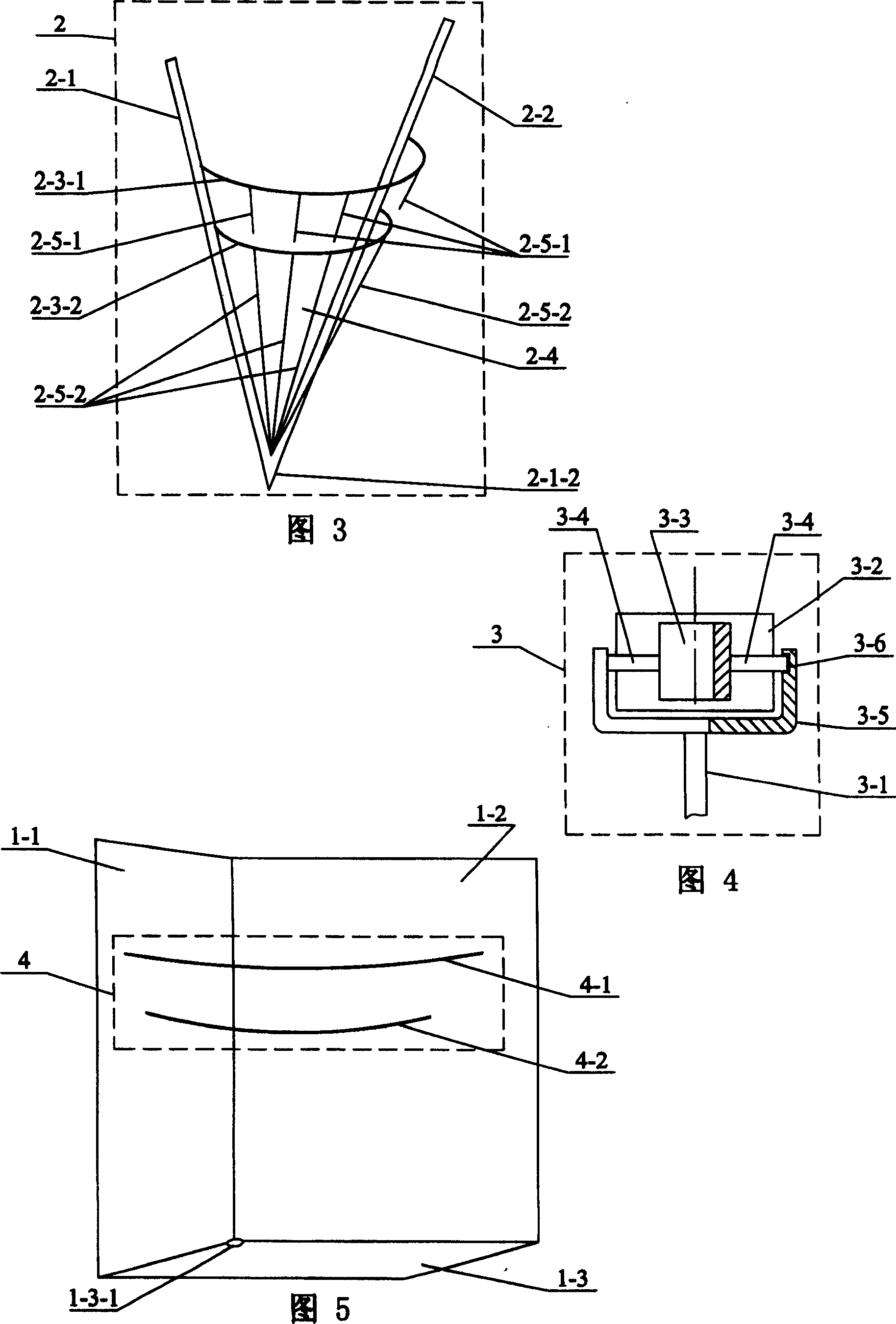
[0005] Specific implementation mode one: (see Figure 1-Figure 6) This embodiment is made up of three-dimensional skateboard 1, rigid body rotor 2, speed perpendicular device 3, space pole mark 4, space pole surface 5; The two planes of the left skateboard 1-1 and the right skateboard 1-2 are fixed together orthogonally; 1. The base plate 1-3 at the intersection with the right slide plate 1-2 is provided with a small conical pit 1-3-1; the rigid rotor 2 is a semi-cone whose orthogonal cross-section is a semi-ellipse, and is formed by the left shaft 2-1. , right shaft rod 2-2, upper body pole mark 2-3-1, lower body pole mark 2-3-2, straight rod 2-5-1, straight line 2-5-2, upper body pole mark 2- The two ends of 3-1 are respectively fixed on the upper part of the left shaft 2-1 and the right shaft 2-2, and the lower body pole 2-3-2 is arranged below the upper body pole 2-3-1 and its two ends respectively fixed on the left shaft rod 2-1 and the right shaft rod 2-2, the upper en...

specific Embodiment approach 2

[0006] Specific implementation mode two: (see Figure 7 ) The difference between this embodiment and the specific embodiment 1 is that the straight rod 2-5-1 and the straight line 2-5-2 on the conical generatrix of the rigid body rotor 2 are replaced by the pole surface 2-4' of the transparent plate body, and the space The E straight rod 5-1-1 and the F straight line 5-1-2 on the tapered busbar of the pole surface 5 are replaced by the pole surface 5' of the transparent plate space, on the left speed vertical line 3-1-1 and the right speed vertical line 3 - The pole surface 2-4' of the transparent plate body at the pole mark 2-3-2 of the lower body where the cross point of 1-2 moves laterally has a transverse slit 2-3-2-1 on the polar surface of the transparent plate space There is a transverse gap 4-2-1 at the position of the B space pole 4-2 on the 5′, so that the crossed left velocity vertical line 3-1-1 and the right velocity vertical line 3-1-2 can pass horizontally in th...

specific Embodiment approach 3

[0007] Specific implementation mode three: (see Figure 8 ) The difference between this embodiment and the specific embodiment 1 is that the straight rod 2-3-4 on the rigid rotor 2 is replaced by the added next No. body pole 2-3-3 and the next No. 2 body pole 2-3-4 5-1 and straight line 2-5-2, and add C space polar mark 4-3 and D space polar mark 4-4 to replace E straight bar 5-1-1 and F straight line 5-1 on space polar plane 5 -2; The next No. body pole mark 2-3-3 is set on the lower side of the lower body pole mark 2-3-2, and its two ends are respectively fixed on the left shaft rod 2-1 and the right shaft rod 2-2, and the bottom No. 2 body pole mark 2-3-4 is arranged on the lower side of the next No. body pole mark 2-3-3, and its two ends are respectively fixed on the left shaft rod 2-1 and the right shaft rod 2-2, and the C space pole The trace 4-3 is located at the lower side of the B space pole 4-2, and its two ends are respectively fixed on the left slide 1-1 and the r...


PUM


Abstract

The utility model relates to a demonstration teaching aid for the dynamic relationship between the instantaneous center, the polar trace, the instantaneous axis and the polar surface of a fixed-point rotation of a rigid body, which relates to a demonstration teaching aid for the content of rigid body mechanics in physics teaching. Each body pole mark (2-3-1), (2-3-2) of the present invention rolls tangentially relative to each space pole mark (4-1), (4-2) respectively, and each speed perpendicular device (3) Sliding on the orthogonal left skateboard (1-1) and right skateboard (1-2) respectively, each speed vertical line (3-1-1), (3-1-2) is perpendicular to each speed vertical line device The velocity direction of (3) intersects and slides at the tangent points of each body pole and each space pole to represent each dynamic instant center (3-1-3), and the connection line of each dynamic instant center at each height represents the dynamic instant axis ( 3-1-4). The body polar face (2-4) rolls relative to the space polar face (5) and is tangent to the instantaneous axis. The invention has the advantages of novel design, clear structure, and can vividly demonstrate the three-dimensional space position dynamic relationship among instantaneous center, body pole, space pole, instantaneous axis direction, body pole surface and space pole surface.

Description

Technical field: [0001] The invention relates to a demonstration teaching aid for rigid body mechanics content in physics teaching. Background technique: [0002] Fixed-point rotation of a rigid body is an important and difficult content in rigid-body mechanics. The concepts of instantaneous center, pole trace, instantaneous axis, and polar surface are introduced to describe the rigid-body rotation. These points, lines, and surfaces play an important role in describing the fixed-point rotation of a rigid body, but They are invisible, intangible, and can only be described and understood by imagination, so these concepts are very abstract and difficult to understand. The concept of instantaneous center and pole is the basis of the concept of instantaneous axis and polar surface. There is an internal connection between them, so a visual space is established to describe the dynamic relationship between the instantaneous center, pole, instantaneous axis and polar surface. The st...

Claims


Application Information

Patent Timeline
Patent Type & Authority Patents(China)
IPC IPC(8): G09B23/10
Inventor 孙正和曲士良
Owner HARBIN INST OF TECH AT WEIHAI
Learn More