
Motion-transfering device of motor-vehicle fan co-axially operated with connection system

A coolant and motor vehicle technology, applied in the direction of coolant flow control, power plant, power plant cooling combination layout, etc., can solve the problems of impossibility to realize the fan no-load condition, increase of production cost, high responsibility, etc.

Inactive Publication Date: 2006-10-18
BARUFFALDI
View PDF2 Cites 0 Cited by
  • Summary
  • Abstract
  • Description
  • Claims
  • Application Information

AI Technical Summary

Problems solved by technology

[0010] Such a solution is, for example, a device described in DE-3203143, in which the crankshaft is connected to the rotor of an electromagnetic clutch, driven directly by the engagement of an armature connected to the fan, however at low speeds the rotation with the transmission shaft is utilized. Produced by the engagement between the conducting disc of the hood and the permanent magnets associated with the fan, said engagement results in motion transmission at low speeds due to relative sliding between the two parts
[0011] However, this solution makes it impossible to achieve the no-load condition of the fan
[0012] In order to overcome this defect, a coupling is described in the EP-0,317,703 document, which adopts the solution disclosed in the aforementioned DE-3203143 patent document, and also contemplates setting a second electromagnetic clutch, which is connected with other The three different operating conditions mentioned above can be obtained with the matching of components, however, it requires a special bearing arrangement, which is not standard and is expensive and difficult to manufacture
[0013] In fact, both solutions have structural limitations, manifested in the fact that the low speed of the fan is determined by the size of the permanent magnets required for the operation of the clutch, therefore it is not possible to adjust the fan within a variable range according to the actual temperature conditions of the engine low speed rotation
[0014] In addition, the arrangement is expected to require a specific configuration of the engine compartment of the motor vehicle, especially in the case of a fan supported by a fixed shaft carrying a pulley, requiring large Protruding out of the rotating mass for positioning, this has various disadvantages, leading in particular to the need for brackets and fixings for the whole device, which further increases the size, due to the presence of other engine components in the engine compartment, appears Technical difficulties in component construction, resulting in an overall increase in production costs

Method used


Image

  • Motion-transfering device of motor-vehicle fan co-axially operated with connection system
  • Motion-transfering device of motor-vehicle fan co-axially operated with connection system
  • Motion-transfering device of motor-vehicle fan co-axially operated with connection system

Examples


Embodiment Construction

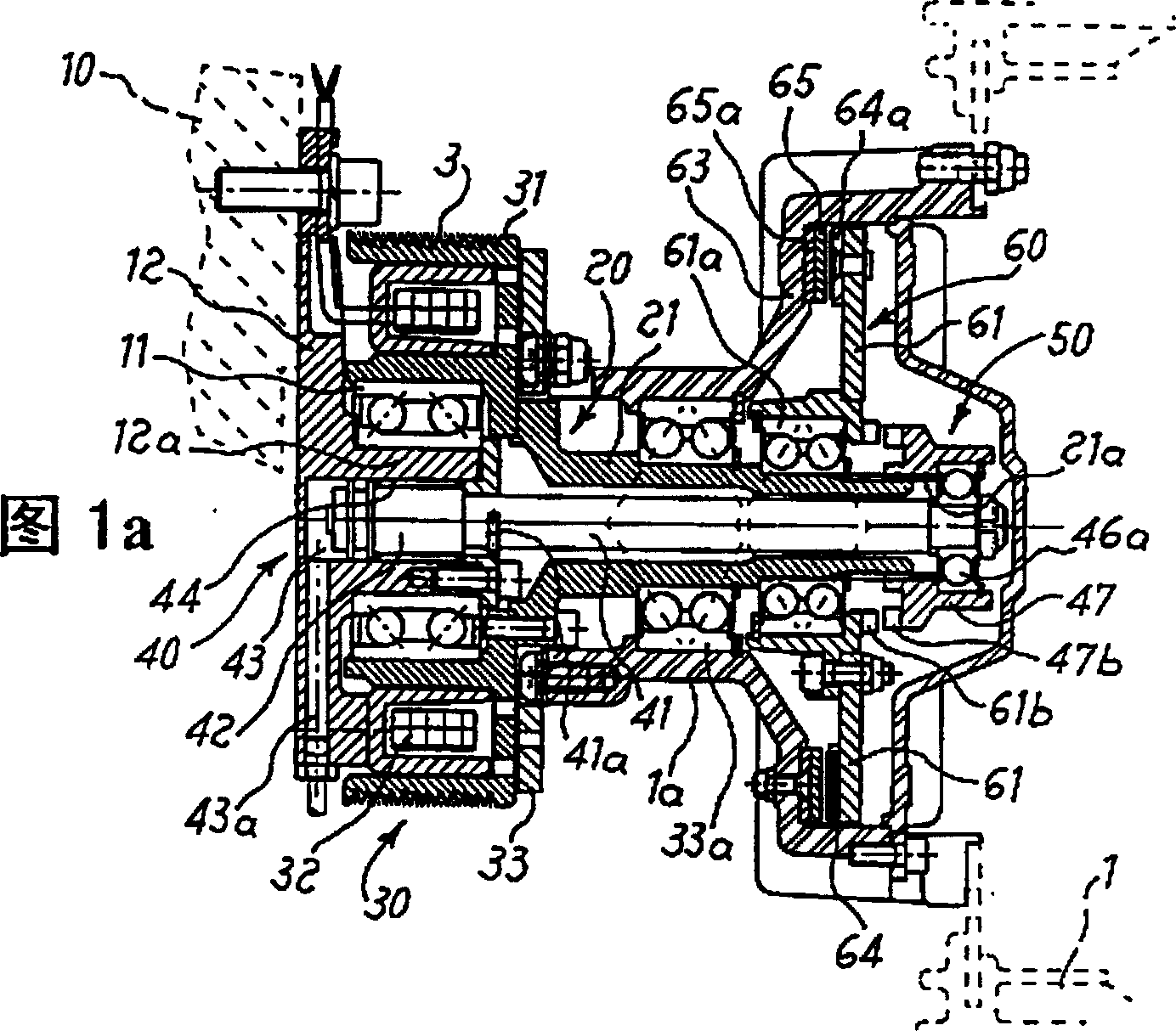
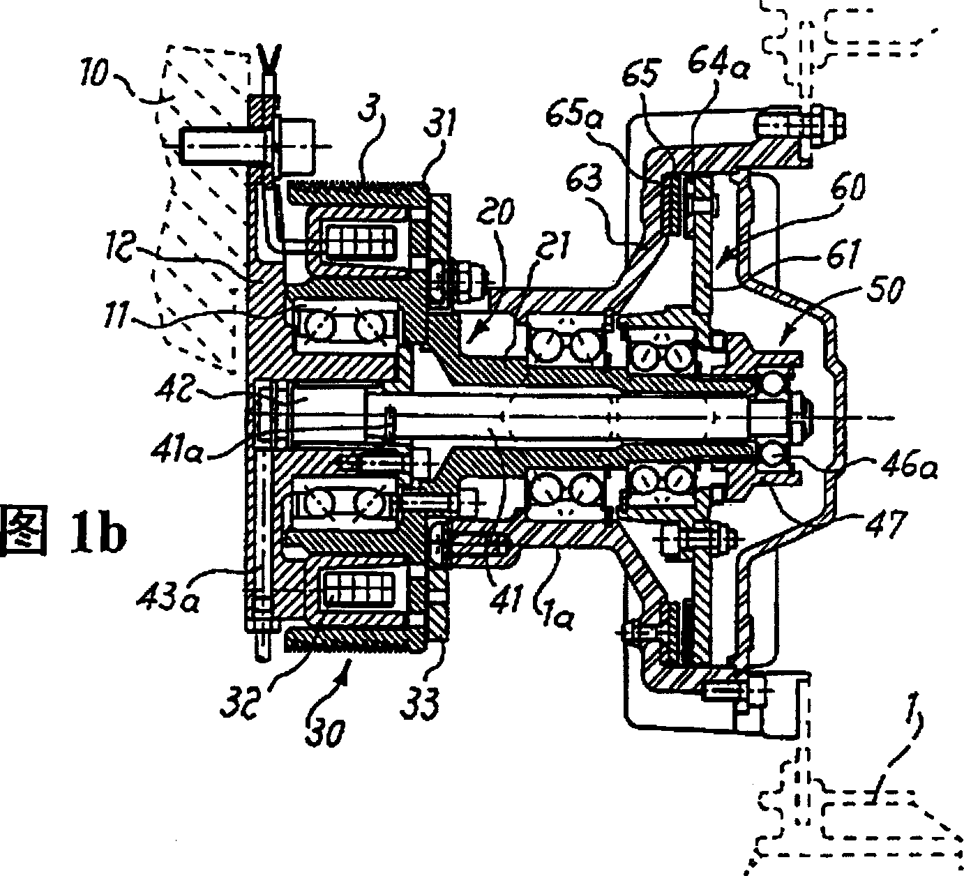
[0023] As shown in Figures 1a, 1b, the means for transmitting motion to the motor vehicle cooling fan 1 is installed between the fan 1 itself and a transmission shaft 20 integral with a pulley 3 connected to the crankshaft by a belt (not shown), For the convenience of description below, "longitudinal" will be understood as a direction parallel to the longitudinal axis of the transmission shaft 20 .

[0024] In further detail, the transmission shaft comprises a hollow bushing 21, one end of which is connected to a rotor 31 integral with the pulley 3, said rotor being mounted on a bearing 11 keyed to the On a suitable hollow extension 12a of a support flange 12 integrally connected with the base body 10 of the engine.

[0025] The rotor 31 constitutes the rotating element of the electromagnetic clutch 30 formed by an annular electromagnet 32, the annular electromagnet 32 ​​is concentric with the rotor 31, the electromagnet is placed between the rotor 31 and the fixed flange 12, ...


PUM


Abstract

A device for transmitting motion to a fan (1) for cooling motor vehicle coolant, comprising: a motion initiating device (3, 21) on which the fan (1) is assembled through an idle support (1a); A first electromagnetic clutch (30); a second clutch (60; 160; 260; 360); a device (50; 150; 250; 350) for engaging / disengaging the second clutch, which device includes a relative A mobile starting element (41) that is coaxially movable in two directions with the movement starting device (3; 21); a connecting device (47; 147; 247c; 347), which is coaxially fixed and moves with the movement starting device (3; 21) ) rotates and is connected with the mobile activation element (41).

Description

technical field [0001] The invention relates to a device for transmitting motion to a fan for cooling a coolant in a motor vehicle. The device includes a first electromagnetic clutch, a second clutch and means for engaging / disengaging the second clutch, and also includes an actuating element that moves coaxially in both directions relative to the motion generating means, but in rotation It remains unloaded. Background technique [0002] As is well known, in the prior art related to cooling the coolant contained in the motor vehicle radiator, it is necessary to forcefully blow air to the surface of the radiator in order to dissipate the heat in the coolant to the outside as soon as possible, said The forced air flow is created by the rotation of a fan, usually mounted directly on the crankshaft or on the water pump shaft, or on a fixed driven shaft that drives a pulley driven by a belt driven by the crankshaft. [0003] It is well known that the fan must start spinning only...

Claims


Application Information

Patent Timeline
IPC IPC(8): F01P7/08B60K11/06F01P7/04F16D25/08F16D27/12F16D39/00
CPCF01P7/04F01P7/046F01P7/081F16D25/086F16D27/12F16D39/00
Inventor 皮尔卡罗·博法利卡罗迪奥·贝尔奥提艾尔米尼奥·德波利法比奥·纳塔勒
Owner BARUFFALDI
Learn More