Drilling and reaming machine

A technology of drilling, expanding and drilling bits, which is applied in the directions of rotary drilling rigs, drilling bits, and earth-moving drilling and mining, etc., can solve the problems of slow speed, reduced pile bearing capacity, and inconvenient operation.

Inactive Publication Date: 2006-10-25
郭明洙
View PDF0 Cites 0 Cited by
  • Summary
  • Abstract
  • Description
  • Claims
  • Application Information

AI Technical Summary

Problems solved by technology

But for a long time, in order to obtain the enlarged pile hole at the bottom, after drilling a straight hole with a long auger drill or a reverse circulation water drill, use a reaming drill bit to expand the hole, and then use a bucket or water to flush the floating soil at the bottom of the hole. Get it on the ground, to get such a drill hole, you need to use two kinds of equipment to construct separately, which has the disadvantages of slow speed, inconvenient operation, and poor stress state of the pile type. In addition, because there is more floating soil at the bottom of the hole, the pile bearing capacity reduce
In the 1970s and 1980s, a drilling rig with integrated drilling and expansion and double-tube double-helical drill bits came out. This kind of drilling rig can be unearthed continuously and form a hole at one time. However, due to the large internal and external friction resistance, the hole depth can only reach 4.5 meters. , due to the inability to adapt to the requirements of deep hole construction, no commercial products have been formed so far.

Method used


Image

  • Drilling and reaming machine
  • Drilling and reaming machine
  • Drilling and reaming machine

Examples


specific Embodiment approach 1

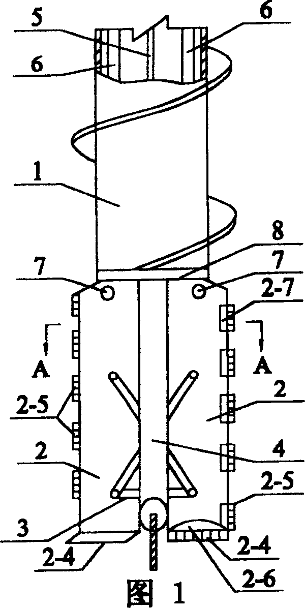
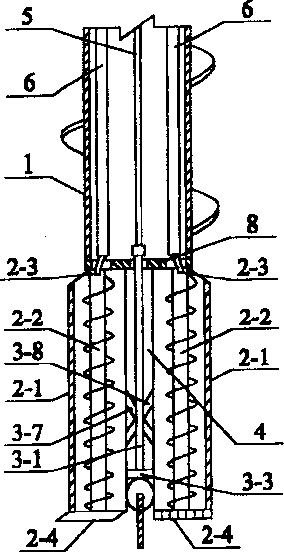
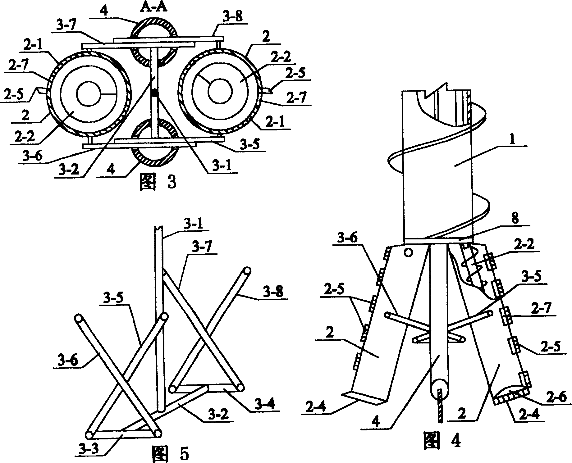
[0005] Specific embodiment one: (see Fig. 1) present embodiment is made up of motor, speed reducer, auger rod 1, pipe drill bit 2, tensioner 3, reinforcing pipe 4, tensioning pipe 5, connecting rod 6, hinge 7, method Composed of flange 8; the rotation of the motor drives the output shaft of the reducer to rotate, the output shaft of the reducer drives the rotation of the auger rod 1, the lower end of the auger rod 1 is fixed with a flange 8, and the lower end of the flange 8 is fixed with two hinges 7, two The hinge 7 is respectively hinged and fixed to the upper ends of the two pipe drill bits 2, the two reinforcement pipes 4 are arranged parallel to the two pipe drill bits 2, the upper ends of the two reinforcement pipes 4 are respectively fixed on the flange 8, and the tensioner 3 is fixed on the two The middle and lower part between the two reinforcement pipes 4, the tension pipe 5 and the two connecting rods 6 are arranged in the auger rod 1 respectively. (See figure 2 ,...

specific Embodiment approach 2

[0006] Specific implementation mode two: (see figure 2 , Figure 6 ) The difference between this embodiment and the specific embodiment one is that the two connecting rods 6 in the auger rod 1 are replaced by a connecting pipe 9, the auger rod 1 is replaced by a thin auger rod 12, and in the thin auger rod 12 A connector 10 is added between the lower end of the lower end and the flange 8, and the connector 10 consists of a connector box 10-1, a large gear 10-2, a large gear shaft 10-3, two small gears 10-4, two small The gear shaft 10-5 is composed of; the large gear 10-2 is fixed on the large gear shaft 10-3, the large gear 10-2 is arranged in the connector box 10-1, and the two small gears 10-4 are respectively fixed on two On the pinion shaft 10-5, two small gears 10-4 are respectively fixed on both sides of the large gear 10-2 in the connector box 10-1, and the two small gears 10-4 mesh with the large gear 10-2 respectively , the upper end of the large gear shaft 10-3 pa...


PUM


Abstract

The utility model relates to an improvement of the structure of a drilling and expanding machine used for pile foundation construction in civil engineering. The present invention is made up of motor, speed reducer, auger rod (1), pipe drill bit (2), tensioner (3), reinforcing pipe (4), tensioning pipe (5), connecting rod (6), hinge (7) ), a flange (8); the rotation of the motor drives the output shaft of the reducer to rotate, and the output shaft of the reducer drives the auger rod 1 to rotate, and the lower end of the auger rod (1) is fixed with a flange (8), and the flange (8) Two hinges (7) are fixed at the lower end of the lower end, and the two hinges (7) are respectively hinged and fixed with the upper ends of the two pipe drill bits (2), and the two reinforcing pipes (4) are arranged in parallel with the two pipe drill bits (2). The upper ends of the two reinforcing tubes (4) are respectively fixed on the flanges (8), the tensioner (3) is fixed at the middle and lower part between the two reinforcing tubes (4), the tensioning tube (5), two connecting rods (6) are respectively arranged in the auger rod (1). The invention has the advantages of combining drilling and expansion, fast hole forming speed, deep pile hole, large diameter of hole expansion, good stress state at the pile end, and less floating soil left at the bottom of the hole. Therefore, the bearing capacity of the pile can be greatly improved and the construction cost can be reduced.

Description

technical field [0001] The invention relates to an improvement of the structure of a drilling and expanding machine used for pile foundation construction in civil engineering. Background technique [0002] At present, in the construction of pile foundations, in order to improve the bearing capacity of piles, the bottom of the pile hole is often enlarged, which not only increases the bearing area of ​​the pile bottom, but also does not increase the cost of the pile foundation much. But for a long time, in order to obtain the enlarged pile hole at the bottom, after drilling a straight hole with a long auger drill or a reverse circulation water drill, use a reaming drill bit to expand the hole, and then use a bucket or water to flush the floating soil at the bottom of the hole. Get it on the ground, to get such a drill hole, you need to use two kinds of equipment to construct separately, which has the disadvantages of slow speed, inconvenient operation, and poor stress state of...

Claims


Application Information

Patent Timeline
Patent Type & Authority Patents(China)
IPC IPC(8): E21B3/00E21B10/32E02D5/44
Inventor 郭明洙郭海龙
Owner 郭明洙
Why Eureka
Try Eureka