

Polymer fibre web manufacturing device and method
A polymer fiber, charge induction technology, used in wet spinning, textile and papermaking, induction discharge jetting, etc., can solve the problem that the technology for high-speed manufacturing of polymer fiber webs has not yet been developed.
- Summary
- Abstract
- Description
- Claims
- Application Information
AI Technical Summary
Problems solved by technology
Method used
Image

Examples
Embodiment 1
[0070] After stirring and mixing 80g of dimethylacetamide (aimethylacetamide) in a stirrer, put polyvinylidene fluoride (poly Vinylidene fluoride) copolymer (Atochem, Kynar761) into it and stir at 70°C for 24 hours to obtain a transparent high molecular solution.
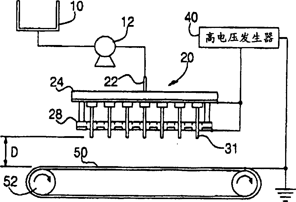
[0071] Put the polymer solution into the barrel 10, apply a voltage of 8-12KV to the conductive plate 30 having 42 single nozzles 32 with a needle 32a and the charge distribution plate 28, and the collector 50 is grounded.
[0072] The distance from the end of the needle 32a of the single nozzle 32 to the charge distribution plate 28 is 1.0 cm, and the height D between the needle 32a and the collector 50 is set to 8 cm.
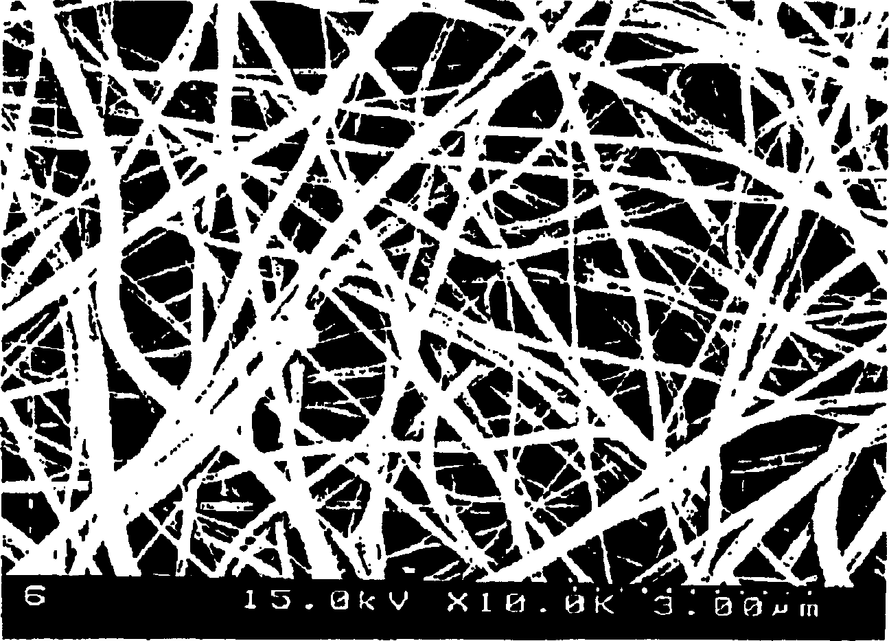
[0073] At this time, the collector 50 used a metal net (web), and the moving speed of the web was 10 m / min. The thickness of the produced porous polymer fiber web was measured with a micrometer, and the results are shown in Table 1.
[0074] Applicable voltage (kV)
Embodiment 2
[0076] After 80 g of acetone (aceton) was stirred and mixed in a stirrer, 20 g of polyvinylidene fluoride copolymer (Atochem, Kynar761) was put into it and stirred at 70° C. for 24 hours to obtain a transparent polymer solution.
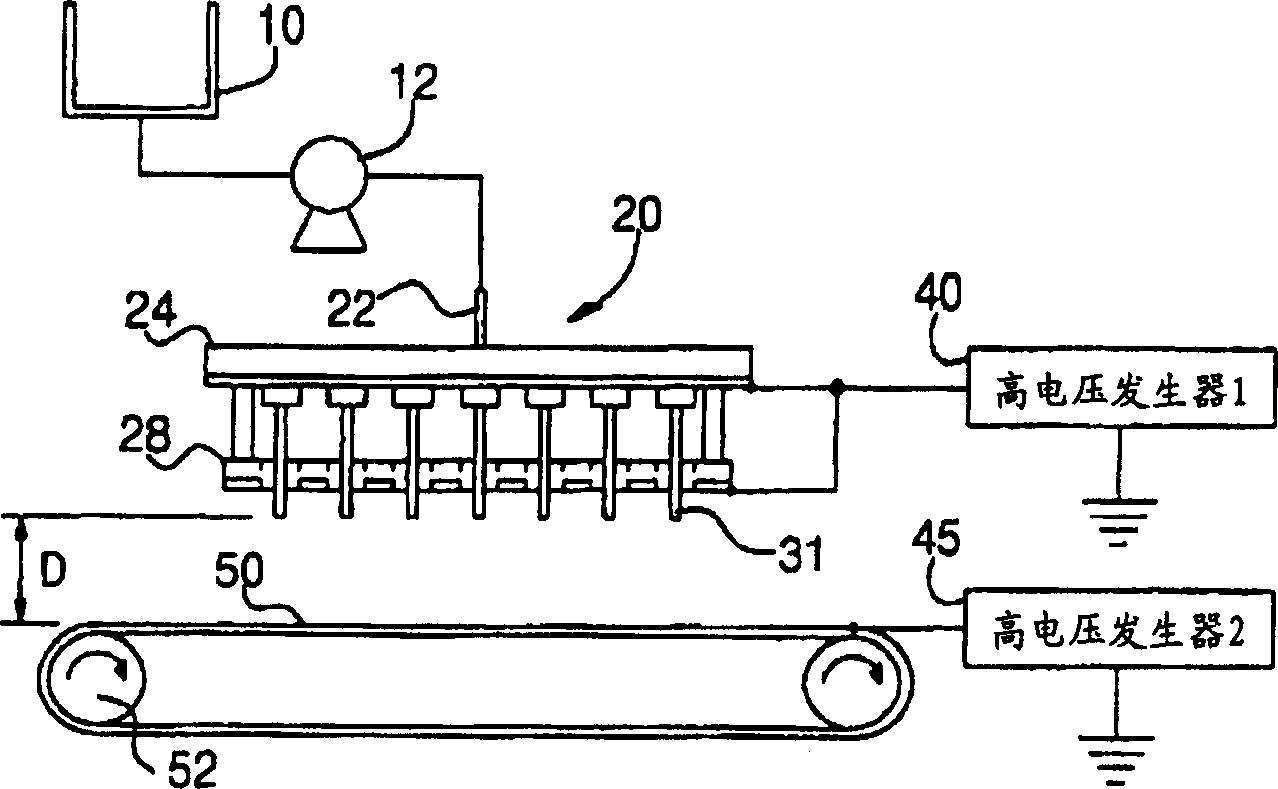
[0077] The polymer solution is put into the barrel 10, and a voltage of 8-12KV is applied to the conductive plate 30 with 5 multi-nozzles 33 and the charge distribution plate 28 with 12 needles 32a, and the collector is grounded.
[0078] The distance from the end of the needle 32a of the multi-nozzle 33 to the charge distribution plate 28 was 1.2 cm, and the height D between the end of the needle of the multi-nozzle 33 and the collector 50 was set to 14 cm.
[0079] At this time, a metal net was used as the collector 50, and the moving speed of the net was 15 mm / min. The thickness of the produced porous polymer fiber web was measured with a micrometer, and the results are shown in Table 2.
[0080] Applicable voltage (kV)
Embodiment 3
[0082] 80 g of dimethylacetamide and 20 g of polyacrylonitrile polymer (PolyScience Co.) were put into a blender and stirred at 70° C. for 24 hours to obtain a transparent polymer solution.
[0083] Put the polymer solution into the bucket 10, apply a voltage of 8-16KV to the conductive plate 30 of the two multi-nozzles 33 with 4 needles 33a and the charge distribution plate 28, and the collector 50 is grounded.
[0084] The distance from the end of the needle 33a of the multi-nozzle 33 to the charge distribution plate 28 was 1.6 cm, and the height D between the end of the needle 33a of the multi-nozzle 33 and the collector 50 was set to 15 cm.
[0085] At this time, a metal plate was used as the collector 50, and the moving speed of the metal plate was 3 m / min. The thickness of the produced porous polymer fiber web was measured with a micrometer, and the results are shown in Table 3.
[0086] Applicable voltage (kV)
PUM
 Abstract
Description
Claims
Application Information