Eureka AIR delivers breakthrough ideas for toughest innovation challenges, trusted by R&D personnel around the world.

Air compressor with energy storage and refrigeration function

A compressed air energy storage and refrigeration device technology, which is applied in the direction of refrigerators, compressors, refrigeration and liquefaction, etc., can solve the problems of low efficiency of energy storage technology, limit the promotion of large-scale, increase the difficulty of management, etc., and achieve the effect of heat exchange Significant, easy to control, simple and flexible structure

Inactive Publication Date: 2006-12-06
ZHEJIANG UNIV
View PDF0 Cites 0 Cited by
  • Summary
  • Abstract
  • Description
  • Claims
  • Application Information

AI Technical Summary

Problems solved by technology

The energy storage technology represented by ice storage is inefficient, and the system is huge and complex, and the initial investment is large, which also increases the difficulty of management and limits its large-scale promotion

Method used


Image

  • Air compressor with energy storage and refrigeration function
  • Air compressor with energy storage and refrigeration function
  • Air compressor with energy storage and refrigeration function

Examples


Embodiment Construction

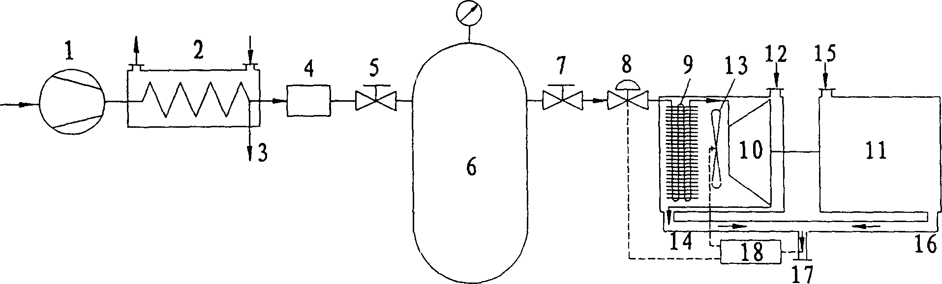
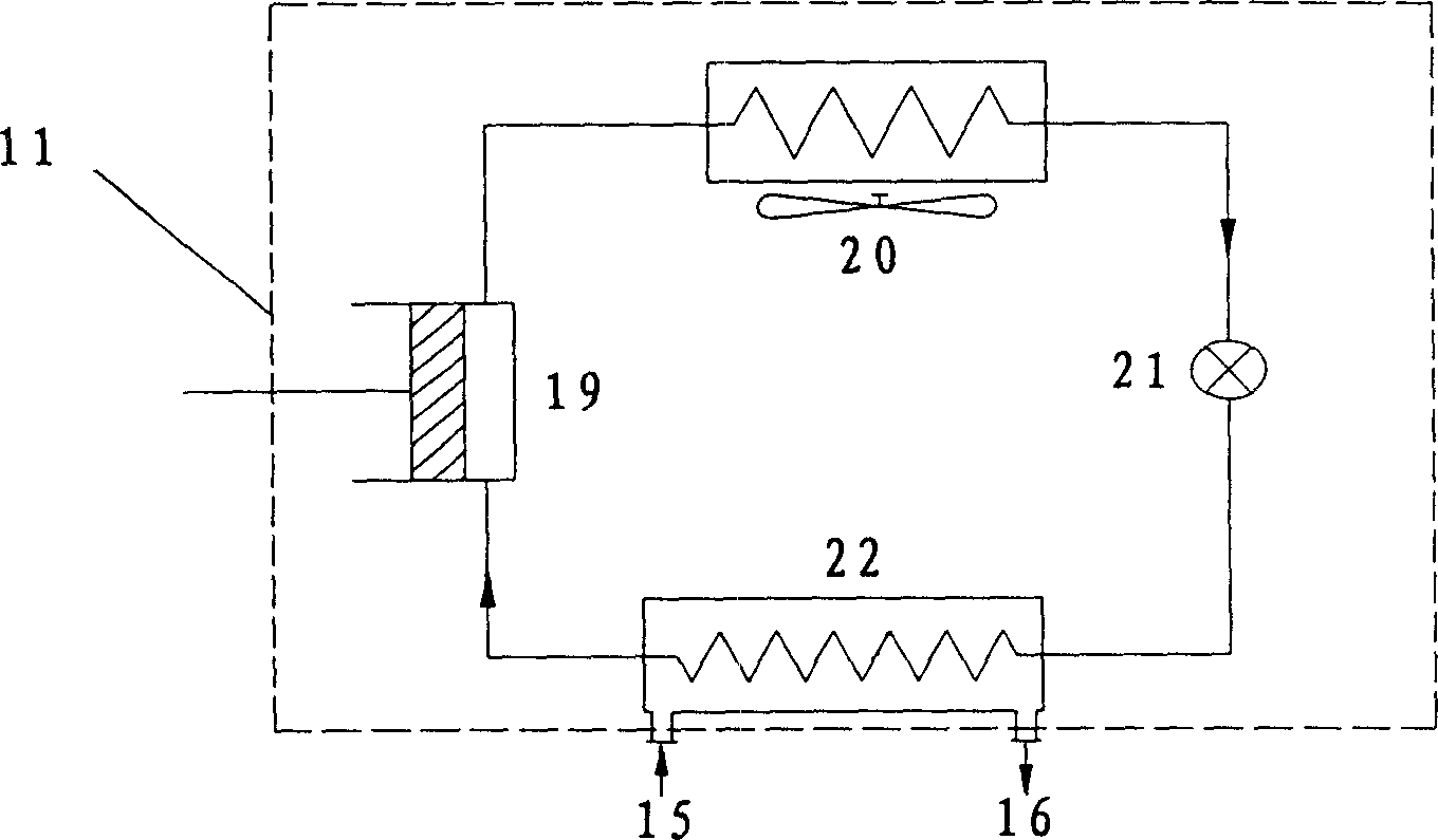
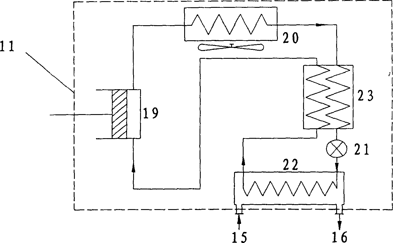
[0017] like figure 1 As shown, the outlet of the compressor 1 is connected to the first cooler 2, the dry filter 4, the first shut-off valve 5, the high-pressure vessel 6, the second shut-off valve 7, the temperature regulating valve 8, the heat exchanger 9 and the expander 10 in sequence , the inlet of the automatic drainer 3 is connected with the other high-pressure gas outlet of the first cooler 2, the heat exchanger 9, the expander 10 and the fan 13 are placed in the first return air duct 12, the outlet of the first return air duct 12 and the expander 10 The outlet is connected to the inlet of the first air outlet pipe 14, the expander 10 is connected to the refrigeration compressor of the compression refrigeration device 11 through a mechanical transmission mechanism, and the air inlet and outlet of the evaporator (22) of the compression refrigeration device 11 are connected to the second circuit respectively. The outlet of the air duct 15 is connected to the inlet of the...


PUM


Abstract

The energy-accumulating and refrigerating compressed air apparatus has air compressor outlet connected successively to cooler, drying filter, the first stop valve, the second stop valve, temperature regulating valve, heat exchanger and expander; automatic water drainer inlet connected to the other high pressure gas outlet; heat exchanger, expander and blower set in the first back draft pipe with outlet connected to the outlet of the expander and the first outtake pipe inlet; expander connected via mechanical transmission mechanism with refrigerating compressor of the compressing refrigerator; evaporator for the compressing refrigerator with air inlet and outlet connected separately to the second back draft pipe outlet and the second back draft inlet; the first and the first outtake pipe outlets connected to the total outtake pipe inlet; and control and regulation equipment with signal input connected to the temperature measuring element of the total outtake pipe and signal output to the temperature regulating valve and the blower.

Description

technical field [0001] The invention relates to a refrigeration device, in particular to a compressed air energy storage refrigeration device. Background technique [0002] Among the existing refrigeration devices, the traditional closed Freon vapor compression refrigeration system is the most perfect and the most widely used. However, this kind of refrigeration device consumes a lot of energy, and is generally used in the peak period of electricity consumption when electricity consumption is relatively concentrated, which easily causes the problem of power shortage for a period of time, and intensifies the contradiction between peak and valley power supply. On the one hand, with the continuous improvement of people's living standards, refrigeration devices such as household air conditioners and refrigerators have begun to enter thousands of households. On the other hand, the continuous development of industry and other industries has also raised more and more demands on the...

Claims


Application Information

Patent Timeline
Patent Type & Authority Patents(China)
IPC IPC(8): F25B9/06
Inventor 陈光明王生龙王勤张绍志
Owner ZHEJIANG UNIV
Why Eureka
Eureka Blog
Learn More