
Internal combustion engine

A technology for internal combustion engines and fuels, applied to internal combustion piston engines, combustion engines, mechanical equipment, etc., can solve problems such as valve flow dynamics or undesired changes in closing performance

Inactive Publication Date: 2006-12-13
VOLKSWAGEN AG +1
View PDF0 Cites 0 Cited by
  • Summary
  • Abstract
  • Description
  • Claims
  • Application Information

AI Technical Summary

Problems solved by technology

Such coking residues can accumulate especially on the intake valves, so as to cause undesired changes in the flow dynamics or closing behavior of the valves

Method used


Image

  • Internal combustion engine
  • Internal combustion engine

Examples


Embodiment Construction

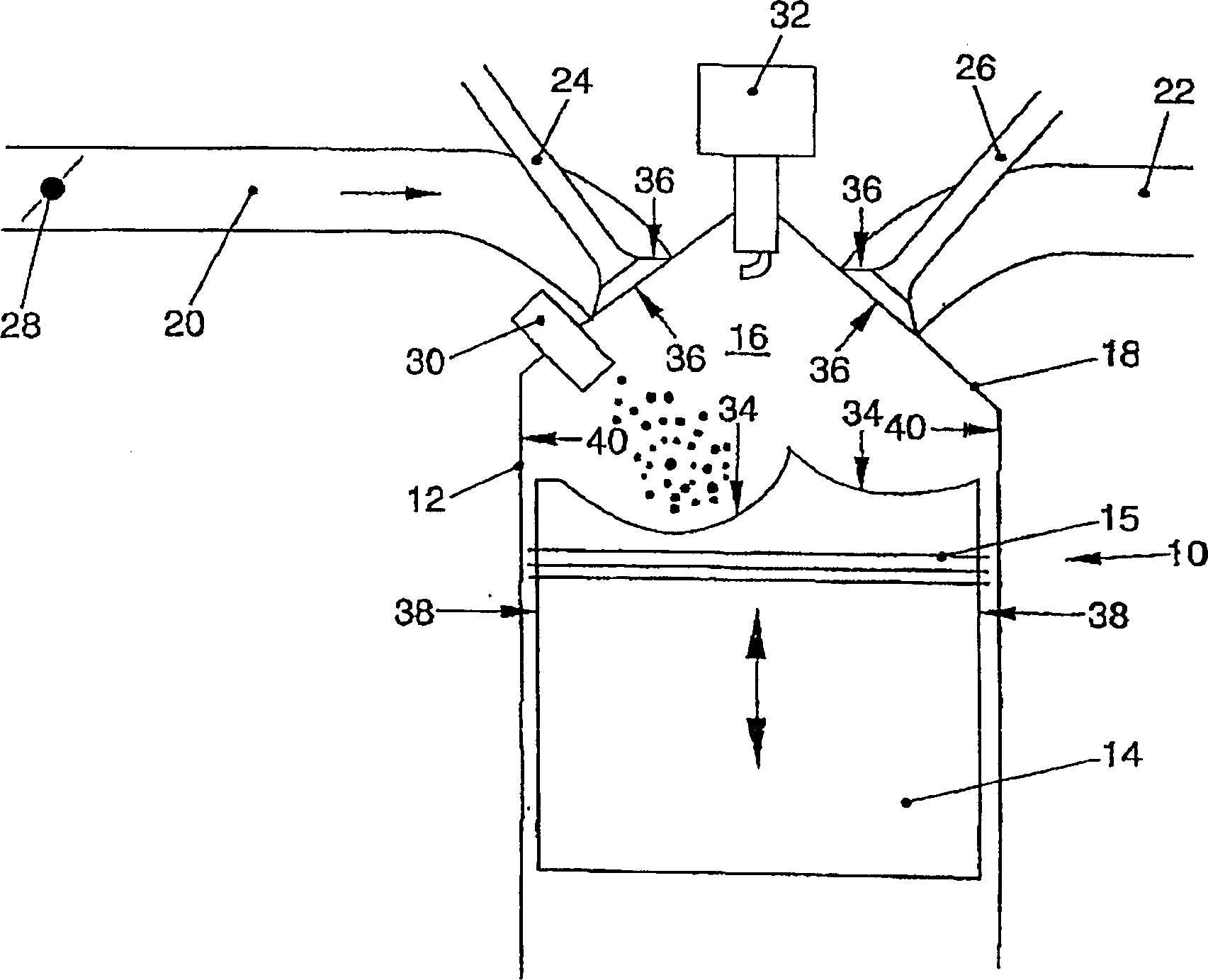
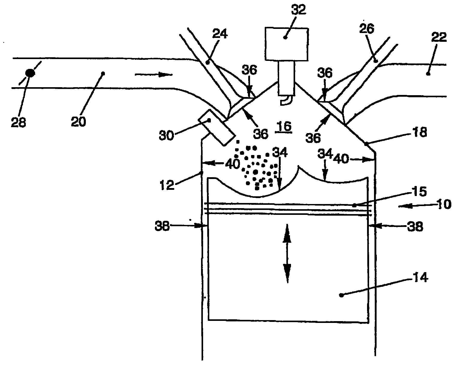
[0015] Only one cylinder 12 is shown in the internal combustion engine, generally designated 10 . It goes without saying that internal combustion engine 10 can also have a plurality of cylinders 12 arranged in different ways. A piston 14 is arranged axially movable in the cylinder 12 , the longitudinal movement of which is converted into a rotational movement of a crankshaft (not shown). A combustion chamber 16 is delimited in the interior of the cylinder 12 by the piston 14 , which is sealed by a piston ring 15 . One side of a cylinder head 18 of the cylinder 12 communicates with an intake pipe 20 through which air is supplied to the combustion chamber 16 , and the other side communicates with an exhaust pipe 22 through which exhaust gas is discharged. The intake manifold 20 and exhaust manifold 22 are opened and closed via intake valves 24 or exhaust valves 26 , which are asynchronously actuated by a camshaft (not shown). It goes without saying that there can also be sever...


PUM


Abstract

The invention relates to an internal combustion engine (10) with at least one combustion chamber (16) enclosed by a cylinder (12) and a piston (14) arranged to move therein. A surface of at least one component of the combustion chamber (16) and / or an adjacent chamber, which comes into contact with the air / fuel mixture for combustion or with motor oil, is provided at least partly with a catalytic coating for oxidation of coking residues.

Description

technical field [0001] The invention relates to an internal combustion engine having at least one combustion chamber. Background technique [0002] Such internal combustion engines (reciprocating piston motors) with external mixing or internal mixing are already known. Such internal combustion engines generally have a plurality of cylinders, an axially movable piston enclosing a combustion chamber in which an incoming air-fuel mixture is combusted. [0003] A known problem with such internal combustion engines is so-called coking residues of the supplied fuel and oil. This is a mixture of asphalt and some complex hydrocarbons that deposit and collect on valves, piston surfaces, intake manifolds, fuel injectors and the top of the combustion chamber. Such coking residues can accumulate in particular on the intake valves, so that they cause undesired changes in the flow dynamics or closing behavior of the valves. Other component surfaces in the combustion chamber, such as pi...

Claims


Application Information

Patent Timeline
Patent Type & Authority Patents(China)
IPC IPC(8): F02B77/02F02B77/04F02B23/00F02F3/14C23C14/08F01L3/02F02B23/10F02B75/12F02F1/42F02F3/10F02M27/02F02M61/14
CPCY02T10/123F02B23/104Y02T10/125C23C14/083F02B77/04F02M27/02F02B77/02F02B2075/125Y02T10/12
Inventor G·苏克G·舍尔克D·雷彭宁
Owner VOLKSWAGEN AG
Learn More