Dual optical communication network for reactor protection systems

A technology of protection system and communication network, applied in the field of dual-optical communication network of reactor protection system, can solve problems such as no failure mode involved

Inactive Publication Date: 2001-04-18
CE NUCLEAR POWER
View PDF0 Cites 5 Cited by
  • Summary
  • Abstract
  • Description
  • Claims
  • Application Information

AI Technical Summary

Problems solved by technology

However, they do not address the failure modes associated with their

Method used


Image

  • Dual optical communication network for reactor protection systems
  • Dual optical communication network for reactor protection systems

Examples


Embodiment Construction

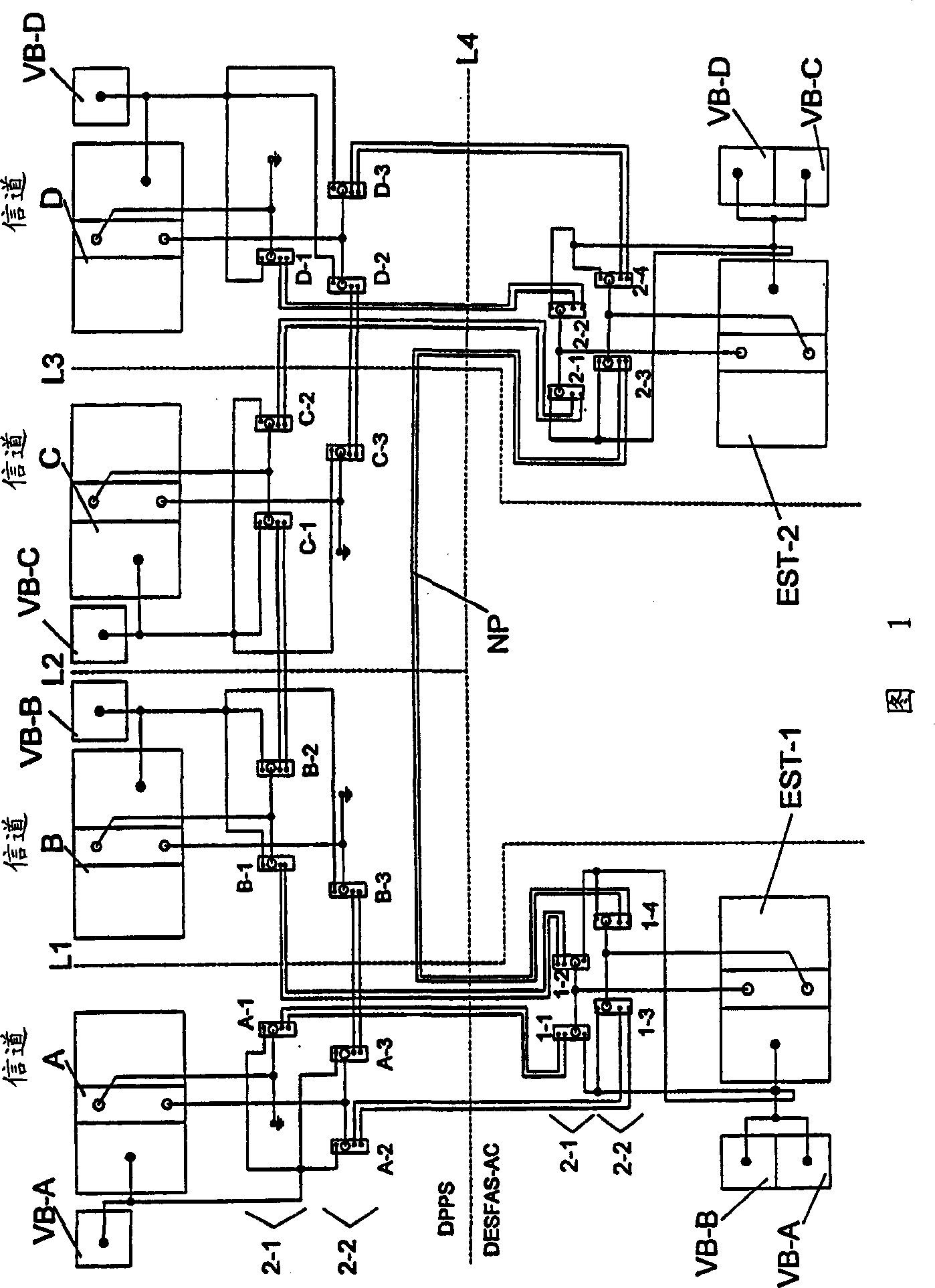
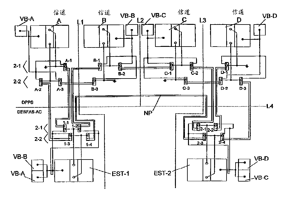
[0011] An ITP network of a nuclear power plant PPS is illustrated in FIG. 1 and generally indicated by reference character 10 . As shown, the network 10 is structured to include four monitoring and control subsystems, designated Channel A, Channel B, Channel C, and Channel D, respectively. These channels are separated by vertical dotted lines L1, L2 and L3 to symbolically illustrate that these channels are physically separated from each other in the nuclear power plant. Each channel includes a bistable processor, an interface signal distributor, an AND logic processor, and an enable logic. These channels communicate with two chains of peripheral safeguards labeled EST-1 and EST-2, respectively. As symbolically illustrated by the horizontal dashed line L4, the peripheral security systems are physically isolated from, and themselves isolated from, the channels from which they receive their control signals. Physical separation of various subsystems from each other increases the...


PUM


Abstract

A communication network for a nuclear power plant protection system includes a plurality of monitoring and control channels, including a first pair of channels which has a first and second channel, the first pair of channels directly communicating through a network of fiber optic data paths with a second pair of channels which has a third channel and a fourth channel; a plurality of engineered safety feature trains, including a first train and a second train, the first train communicating directly with the first pair of channels, and communicating directly with the second train, the second train communicating directly with the second pair of channels, and communicating directly with said first train; a first vital power bus, individually powering the first channel; a second vital power bus, individually powering the second channel, and redundantly powering the first train together with the first vital power bus; a third vital power bus, individually powering the third channel; and a fourth vital power bus, individually powering the fourth channel, and redundantly powering the second train together with the third vital power bus.

Description

Background of the invention [0001] Reactor protection systems require periodic testing. The testing of the reactor protection system requires the exchange of status information between the independent channel of the plant protection system ("PPS") and the chain of peripheral safety measures ("ESF"). Implementing these systems digitally presents the inherent problem of maintaining channel / chain independence while maintaining communication integrity and proper functionality. Typical fiber optic communication networks provide the required electrical isolation and independence between channels and chains. However, they do not address the failure modes associated with them. Brief description of the invention [0002] In order to achieve the purpose and other purposes introduced above, overcome the shortcoming in the prior art system, a main purpose of the present invention is to provide a kind of optical communication network, for exchanging required information between redunda...

Claims


Application Information

Patent Timeline
Patent Type & Authority Applications(China)
IPC IPC(8): G21C7/36G21C17/00G21D3/04
CPCG21D3/04G21C7/36Y02E30/39G21C17/00Y02E30/40Y02E30/00Y02E30/30
Inventor S·J·维尔科斯兹R·R·塞尼查尔G·D·阿尔滕海恩
Owner CE NUCLEAR POWER
Why Eureka
Try Eureka