Improved slide valve in hydraulic copying general pipe for controlling motion of punch hammer in punch

A hammer and header technology, applied in the field of hydraulic profiling header slide valve, can solve the problems of unable to calibrate the support, affecting the accuracy of machining operations, affecting the impact hammer, etc.

Inactive Publication Date: 2007-01-31
欧麦克股份公司
View PDF6 Cites 0 Cited by
  • Summary
  • Abstract
  • Description
  • Claims
  • Application Information

AI Technical Summary

Problems solved by technology

[0012] The second disadvantage is the fact that the plunger rod is mounted to the hammer shaft by a sheet metal bracket, so in this embodiment it is not possible to calibrate the bracket to the minimum tolerances requir...

Method used


Image

  • Improved slide valve in hydraulic copying general pipe for controlling motion of punch hammer in punch
  • Improved slide valve in hydraulic copying general pipe for controlling motion of punch hammer in punch
  • Improved slide valve in hydraulic copying general pipe for controlling motion of punch hammer in punch

Examples


Embodiment Construction

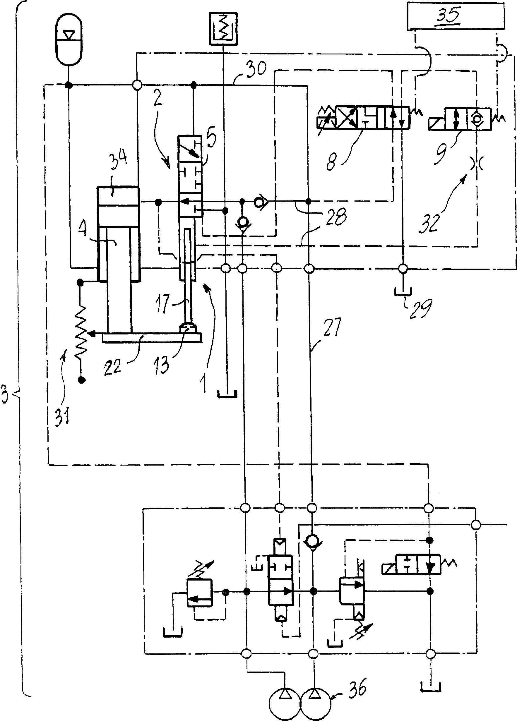
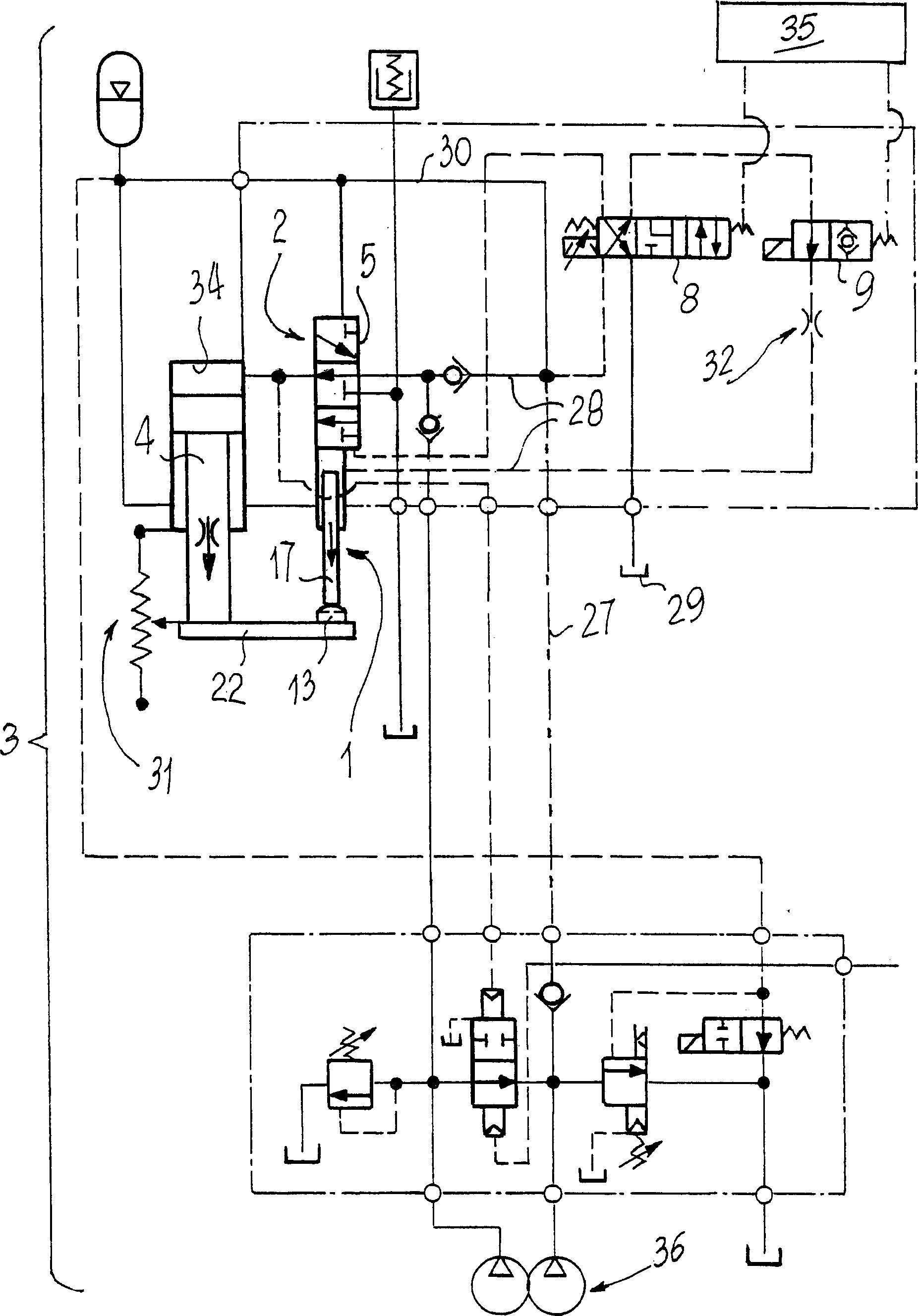
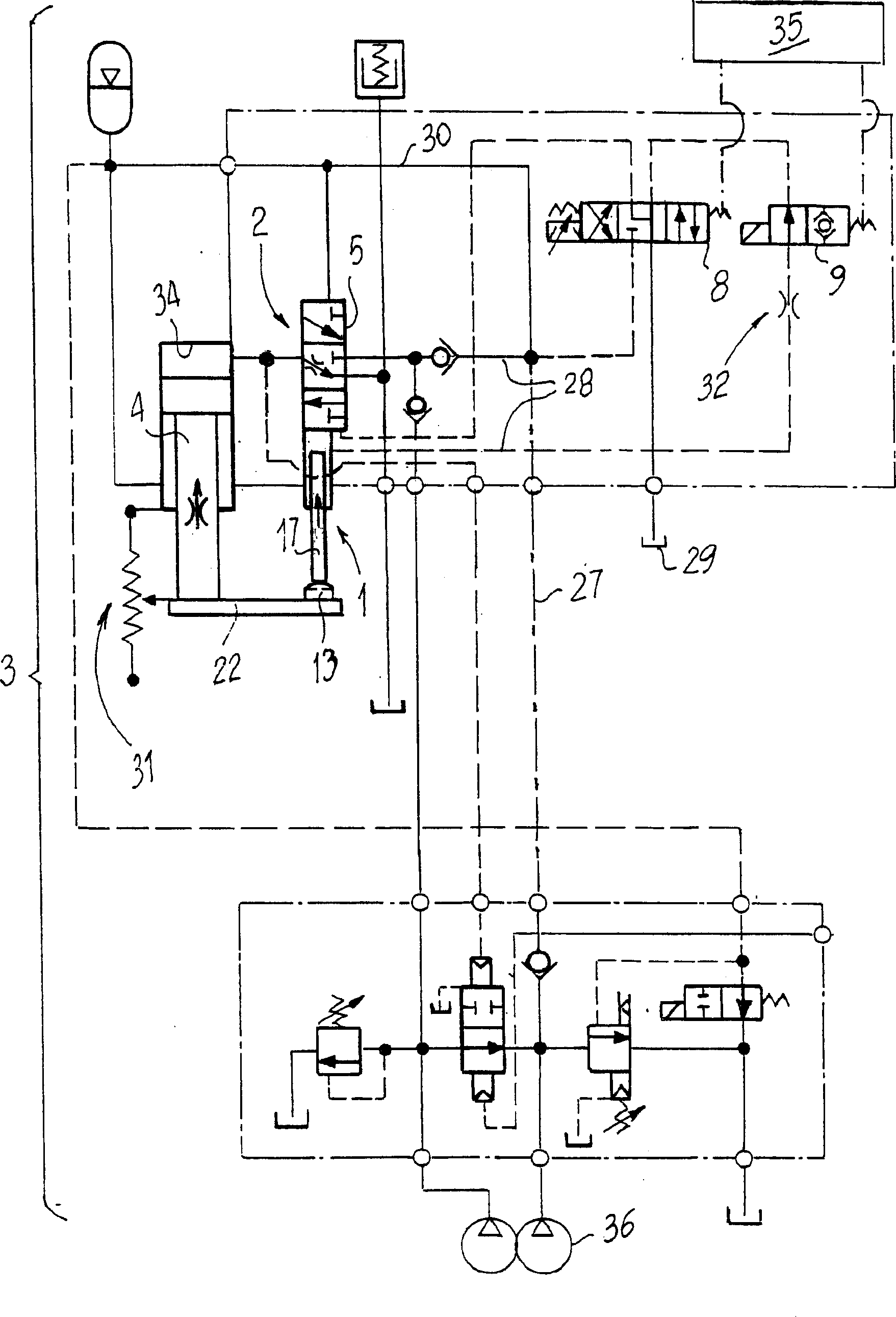
[0023] For the above figures, 1 indicates the slide valve of the profile manifold 2, which slide valve is installed in a hydraulic circuit 3 for controlling the mast movement of the hammer 4 in the press.

[0024] The manifold 2 comprises a body 5 connected by means of hoses with fittings (not shown in the figures) to the hydraulic circuit 3 and equipped with supply holes 6 for pressurized fluid (hydraulic oil) connected to said fittings and discharge hole 7.

[0025] The spool valve 1 is driven by at least one pair of valves 8 and 9 constituting said valve unit, each of which is installed in the hydraulic circuit 3; moreover, the spool valve is movably mounted inside the body 5, machined in a specific bracket 10 Shaped, the spool determines the periodic opening and closing of the holes 6, 7 and 33.

[0026] The movable end 11 of the spool valve 1 communicates with the outside of the body 5 by means of a provided calibration hole 12, and plays the role of cooperating with the...


PUM


Abstract

Improvement in a spool of a copying distributor in a hydraulic circuit for controlling the motion of a cylinder for a hammer in a punching machine, includes a pressurized fluid source in communication with said hydraulic circuit, a distributor body which is connected to said hydraulic circuit through pipe fittings and is formed with pressurised-fluid supply lights and discharge light communicating with said pipe fittings, at least one valve means arranged in said hydraulic circuit to control the said distributor body, a spool slidably mounted in said body and arranged cyclically to open and close the said lights, one operating end of said spool extending outside said distributor body through a calibrated aperture and being arranged to abut against a reference member designed to move rigid with said hammer. The improvement provides for a recess formed in said operating end and having one end thereof blind and its other end open, a pin slidably mounted in said open end and arranged to be displaced therein by pressurised fluid flows controlled by said valve means, and at least one duct formed in said distributor body and arranged to feed pressurised fluid from said fluid source to said recess.

Description

technical field [0001] The present invention relates to a hydraulic copying manifold spool for controlling the movement of a ram in a punch press. Background technique [0002] Fluid manifolds have long been known for use with oil and are used in hydraulic circuits controlling the movement of rams, which are posts that apply loads to tools mounted on punch tool heads, which Equipped with means of alternate calibration strokes designed to implement the control parameters governing the movement of said ram. [0003] More specifically, among said parameters, those governing the stroke speed of the ram are particularly important, as are the alignment of the top and bottom dead centers of the adjustment stroke and the starting point of the punching stroke, which are themselves related to the process to be processed (profiling) ) is related to the thickness of the steel sheet. [0004] The alignment of top and bottom dead centers and the start of stroke as a function of the thic...

Claims


Application Information

Patent Timeline
IPC IPC(8): F15B9/10F15B13/02B30B15/16
CPCF15B9/10B30B15/16
Inventor 兰佐蒂欧金尼奥
Owner 欧麦克股份公司
Why Eureka
Try Eureka