
Method and device for coating with paste

A coating device and paste technology, which are applied to the device, spray device, coating and other directions for coating liquid on the surface, can solve the problem that the coating position accuracy and coating area accuracy cannot be obtained, and it is not easy to control the coating with high precision. The coating amount and the large variation range of the coating amount can improve the coating efficiency, improve the coating shape accuracy, and improve the coating position accuracy.

Inactive Publication Date: 2007-02-07
MURATA MFG CO LTD
View PDF1 Cites 0 Cited by
  • Summary
  • Abstract
  • Description
  • Claims
  • Application Information

AI Technical Summary

Problems solved by technology

[0004] ① The adhesive 5 applied on the ferrite base 4 may flow to the lower side of the ferrite base 4 over time, or even if it does not flow to the lower side, it spreads to the point where the adhesive 5 is not expected to adhere. area, so that sufficient coating position accuracy and coating area accuracy cannot be obtained
[0005] ②In the case of making small products, for example, when it is necessary to apply a small amount of adhesive of about 0.2 to 1 mg, in this case, the method of supplying the adhesive from the dispenser nozzle depends on the distance between the coating object and the dispenser nozzle, the adhesive The temperature and other conditions cause the coating amount to vary widely, and it is not easy to control the coating amount with high precision
[0006] ③In addition, if the accuracy of the coating area and coating pattern is to be improved, it is necessary to rely on a high-precision automatic device to drive the dispenser nozzle, resulting in an increase in equipment costs

Method used


Image

  • Method and device for coating with paste
  • Method and device for coating with paste
  • Method and device for coating with paste

Examples


Embodiment

[0032] Embodiments of the present invention are shown below, and its features are further described in detail.

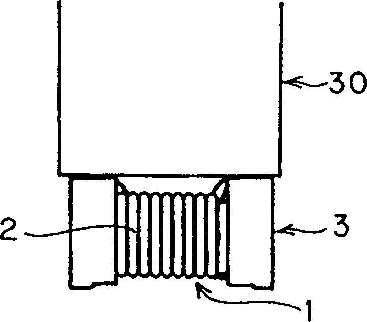
[0033] Such as Figure 5 As shown, in the case of manufacturing a coil component having a structure in which a magnetic core 3 made of ferrite with a metal wire 2 wound on a winding core 1 and a ferrite base 4 are bonded by an adhesive 5, the The case where the adhesive 5 for bonding the magnetic core 3 and the ferrite 4 is applied to the magnetic core 3 will be described as an example.

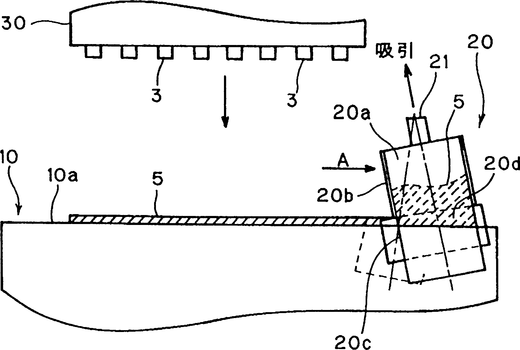
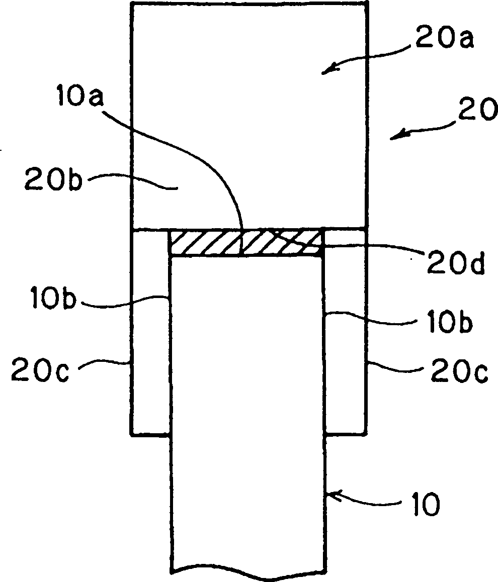
[0034] figure 1 It is a front cross-sectional view of main parts showing a paste application device for carrying out the paste application method of the present invention. figure 2 It is a side view showing the locking relationship between the paste application frame and the paste supply device. image 3 It is a side view showing the state where the coating object (magnetic core) is held by the holding device.

[0035] Such as figure 1 , figure 2 as well as image 3 As sh...


PUM


Abstract

The present invention provides a paste application method and a paste application apparatus excellent in economical property and capable of efficiently applying a paste to a large number of objects to be coated at high precision of the application amount of the paste and the application position. A paste (an adhesive) 5 is supplied by moving a paste supply means 20 along the end face 10a of a paste application jig 10 to apply the paste 5 in a prescribed thickness to the end face 10a of the paste application jig 10 and at the same time, a plurality of objects to be coated (cores) 3 held by a holding means 30 are brought into contact with the paste 5 applied to the end face 10a of the paste application jig 10 to apply the paste 5 to the prescribed positions of a plurality of the object to be coated (cores) 3.

Description

technical field [0001] The present invention relates to a paste coating method and a paste coating device, in particular to a method for coating resins, adhesives, conductive adhesives, resistive adhesives, paste brazing materials, ceramics, etc. A paste coating method and a paste coating device for a paste-like material such as glue. Background technique [0002] For example, if Figure 5 As shown, among the coil components, there is a coil component having a structure in which a magnetic core 3 made of ferrite in which a metal wire 2 is wound around a winding core portion 1 and a ferrite base 4 are bonded with an adhesive 5 . In the manufacture of coil components of this structure, such a method has been used before, that is, as Figure 6 As shown, the ferrite base 4 is filled into the plurality of holding recesses 62 formed on the holding plate 61, the adhesive 5 is continuously supplied by the dispenser nozzle 63, and the dispenser nozzle 63 only moves a specified dista...

Claims


Application Information

Patent Timeline
Patent Type & Authority Patents(China)
IPC IPC(8): B05D1/26B05B13/00H01F41/00H01G4/00B05C1/02B05C3/18B05C3/20B05C5/02B05D1/00B05D1/28B05D7/00H01F41/04H05K3/12
CPCH05K1/092H05K3/1241H05K2203/0126
Inventor 仓野慎一
Owner MURATA MFG CO LTD
Learn More