
Sealing ring type filling device

A sealing ring type, stuffing box technology, applied in sealing, engine sealing, packaging, etc., can solve the problems of shortened life, failure, excessive wear of seals, etc.

Inactive Publication Date: 2007-02-07
HOERBIGER KOMPRESSORTECHNIK HLDG GMBH
View PDF10 Cites 0 Cited by
  • Summary
  • Abstract
  • Description
  • Claims
  • Application Information

AI Technical Summary

Problems solved by technology

[0002] The packing housing of this packing device, which is mostly composed of multiple assembled parts, is still cooled with water or other suitable circulating cooling fluid so as to dissipate the relative movement between the sealed components and the sliding seal fixed in the housing. Frictional heat generated between the parts and thus avoid impermissible temperature rises, which lead to excessive wear of the seals and correspondingly shorten their life or lead to their failure
In addition to the additional costs associated with this, problems can arise, for example, if coolant enters the compressor and thus the process through aged seals or gaps between components of the packing housing

Method used


Image

  • Sealing ring type filling device
  • Sealing ring type filling device
  • Sealing ring type filling device

Examples


Embodiment Construction

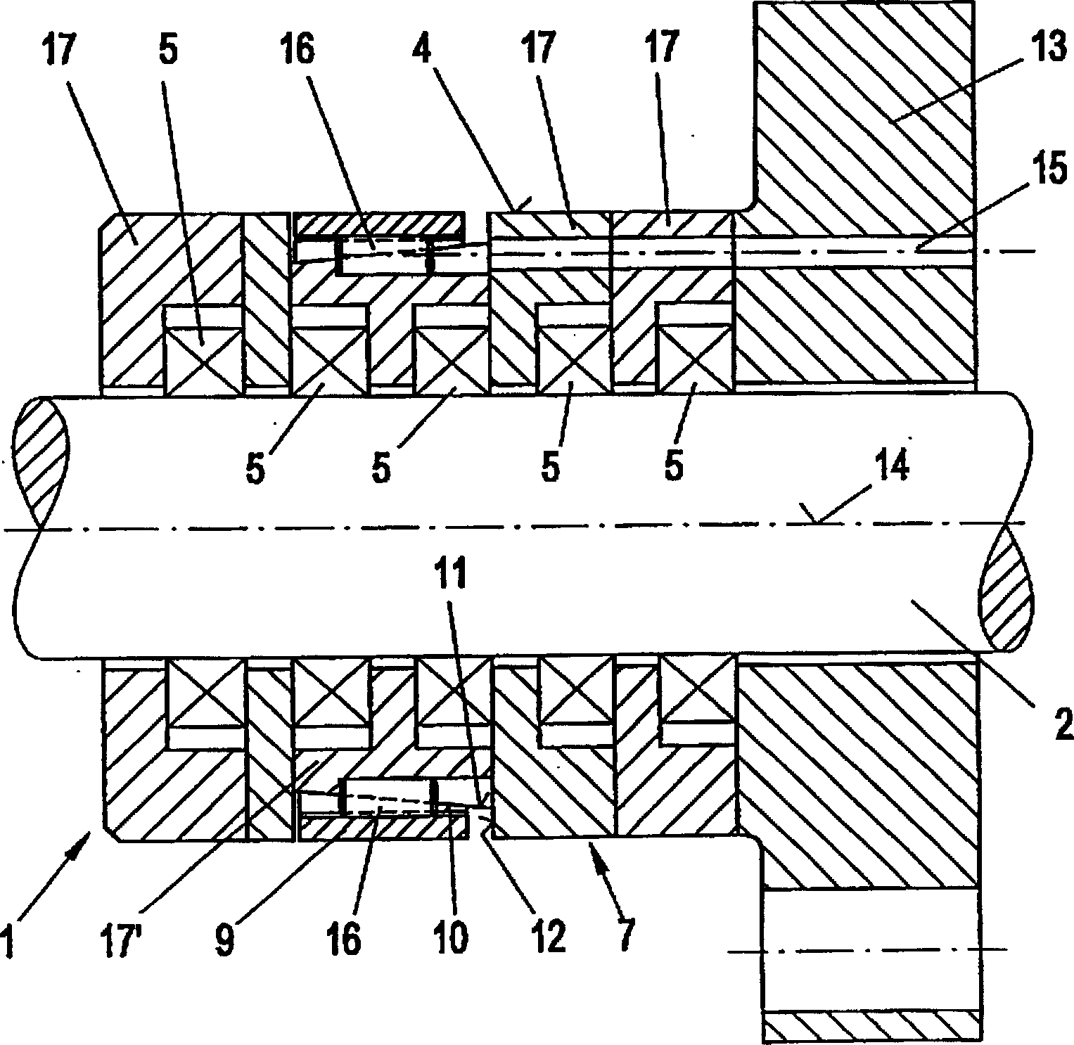
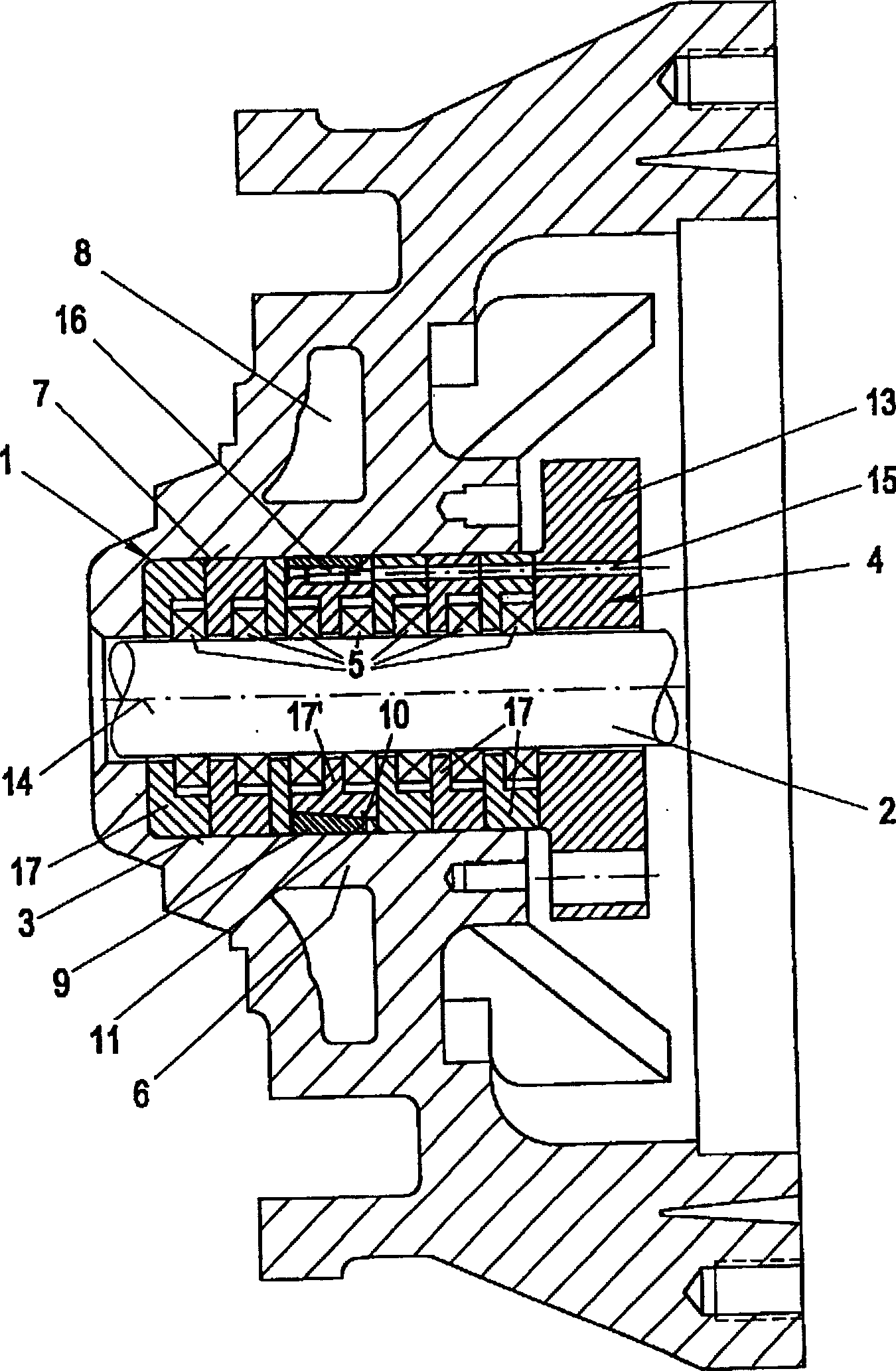
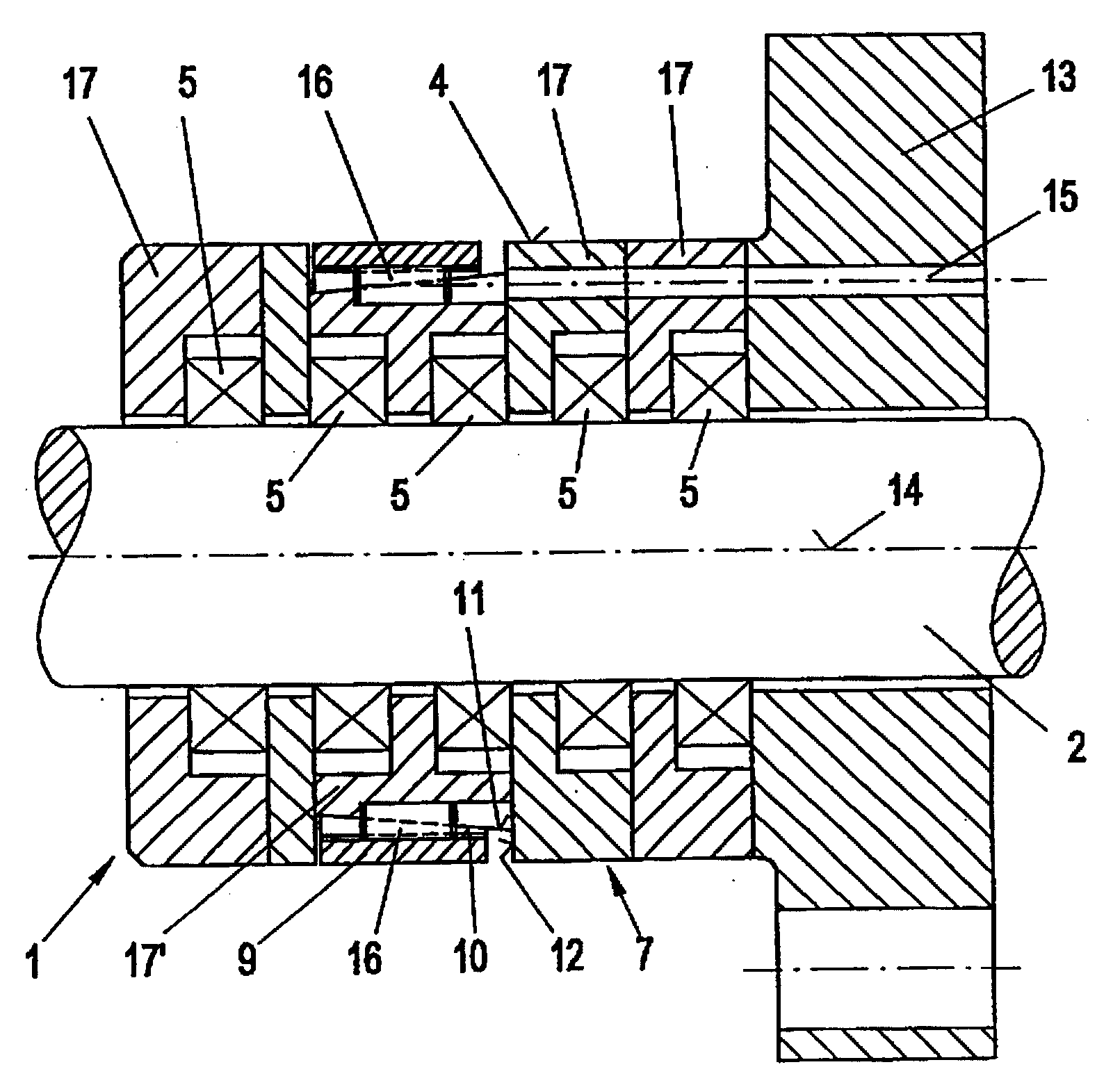
[0013] The following will describe as much as possible figure 1 and figure 2 , wherein in all cases identical or functionally similar components are given the same designation in both figures.

[0014] The sealing ring packing device shown in the two figures is used for sealing the passage of the reciprocating piston rod 2 of a not further shown piston compressor, wherein the piston compressor is used, for example, as a process compressor for various gases . Wherein the stuffing device 1 has a through hole 3 that can be inserted into a stuffing box (see figure 2 ) packing housing 4, a plurality of substantially annular sliding seals 5 are arranged in the packing housing 4, and each sliding seal 5 presses against the sealed moving member (here, the piston rod 2). The type and specific configuration of the sliding seal 5 is no longer important here, it is only important that the frictional heat generated by its friction against the piston rod 2 has to be conducted away from...


PUM


Abstract

The sealing ring packet (1) has a cooled packet casing (4) inserted in the bore for the piston (2) and holding at least one annular slide seal (5). The outer surface (7) of the packet casing has at least one heat transmission sleeve (9) that can expand as far as the inner surface of the bore and which is not separately cooled. The heat transmission sleeve may be a split ring with a conical interior.

Description

technical field [0001] The invention relates to a sealing ring packing device, especially used for sealing the passage of a reciprocating piston rod of a piston compressor. At least one substantially annular sliding seal is accommodated against the moving member to be sealed. Background technique [0002] The packing housing of this packing device, which is mostly composed of multiple assembled parts, is still cooled with water or other suitable circulating cooling fluid so as to dissipate the relative movement between the sealed components and the sliding seal fixed in the housing. Frictional heat generated between the parts and thus avoid an impermissible temperature rise, which leads to excessive wear of the seals and correspondingly shortens their life or leads to their failure. In addition to the additional costs associated with this, problems can arise, for example, if coolant enters the compressor and thus the process through aged seals or gaps between individual par...

Claims


Application Information

Patent Timeline
IPC IPC(8): F16J15/18F04B53/02F16J15/28
CPCF16J15/28Y10S277/93
Inventor 克里斯托弗·D·拉德克利夫
Owner HOERBIGER KOMPRESSORTECHNIK HLDG GMBH
Learn More