
Electron gun possessing multilayer common lenses

An electron gun and a common technology, applied in the field of electron guns, can solve the problems of reducing video image resolution, enlarging electron guns, astigmatism, etc., and achieve the effects of increasing effective diameter, improving resolution, and increasing length

Inactive Publication Date: 2007-02-07
CHUNGHWA PICTURE TUBES LTD
View PDF10 Cites 0 Cited by
  • Summary
  • Abstract
  • Description
  • Claims
  • Application Information

AI Technical Summary

Problems solved by technology

However, increasing the size of the electron gun along the Z axis will cause asymmetric astigmatism (asymmetric astigmatism) in the passing electron beam, which reduces the resolution of the video image.

Method used


Image

  • Electron gun possessing multilayer common lenses
  • Electron gun possessing multilayer common lenses
  • Electron gun possessing multilayer common lenses

Examples


Embodiment 1

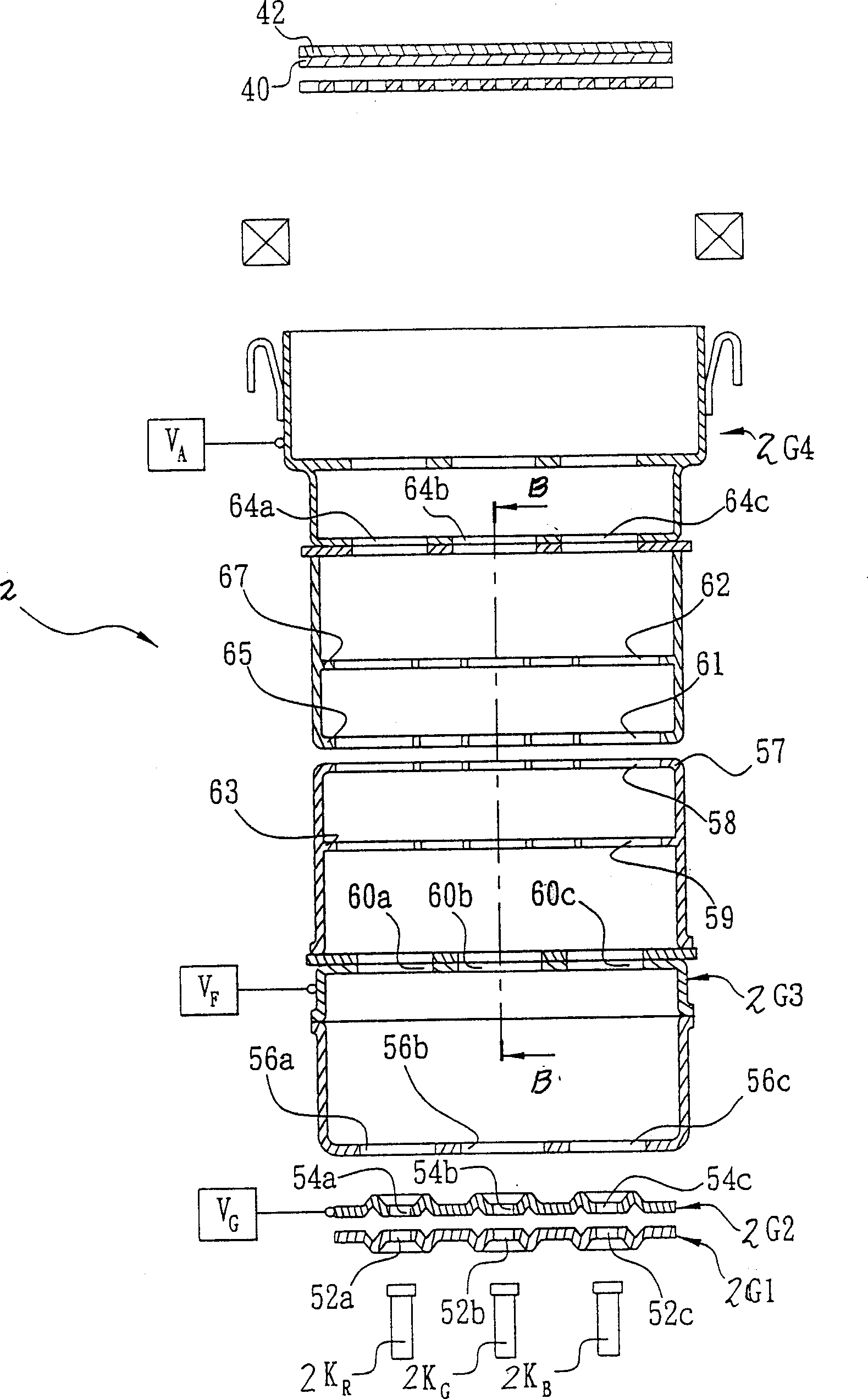
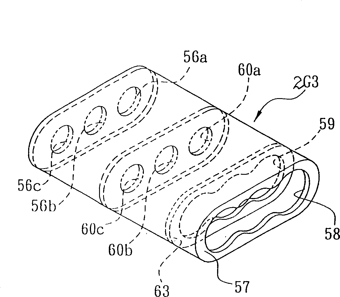
[0028] Such as figure 2 , image 3 , Figure 4 , Figure 5 As shown, the electron gun 2 with multilayer common lens of the present invention is a coaxial bipotential (Inline bipotential) electron gun, which includes a plurality of cathodes 2K that generate multiple groups of energetic electrons R , 2K G , 2K B , set at the cathode 2K R , 2K G , 2K B and the electron beam forming area and the electron lens area between the display screen 42; and make the electron lens area be positioned between the electron beam forming area and the display screen 42; The first group of electrodes composed of control electrodes 2G1, screen electrodes 2G2 and partial focusing grids 2G3 arranged at intervals; the electron lens area includes a second group of electrodes composed of a plurality of other partial focusing grids 2G3 and grids 2G4 arranged at intervals, each The electrodes are provided with at least two sets of common pole holes arranged along the longitudinal axis for electro...

Embodiment 2

[0038] Such as Image 6 , Figure 7 , Figure 8 , Figure 9 As shown, the electron gun 3 with multilayer common lens of the present invention is a quadrupole focusing (quadrupole focusing; QPF) electron gun, which includes a plurality of cathodes 3K that generate multiple groups of energetic electrons R 、3K G 、3K B , set on the cathode 3K R 、3K G 、3K B and the electron beam forming area and the electron lens area between the display screen 42; and make the electron lens area be positioned between the electron beam forming area and the display screen 42; The first group of electrodes composed of control electrodes 3G1, screen electrodes 3G2 and partial focusing grids 3G3 arranged at intervals; the electron lens area includes a plurality of other partial focusing grids 3G3, first grids 3G4, second grids 3G5, The three groups of electrodes formed by the third grid 3G6, each electrode is provided with at least two groups of common pole holes arranged along the longitudinal...


PUM


Abstract

The invention discloses a display device in order to improve resolution of video image, and avoid generating astigmation phenomena of electron beam. The invention includes following parts: multiple cathodes generating multiple electron groups with energies; formation area of electron beam and electron lens area located between cathode and display screen; the electron lens area positioned between formation area of electron beam and display screen. Formation area of electron includes multiple special arranged first group of electrode. Each electrode includes at least one more first holes of pole arranged in line to increase section for electrons with energy to pass through in order to form electron beam. Electron lens area includes multiple special arranged second group of electrode. Each electrode includes at least more than two common holes of pole arranged along longitudinal axis for electrons to pass through in order to form multiple layer common lenses.

Description

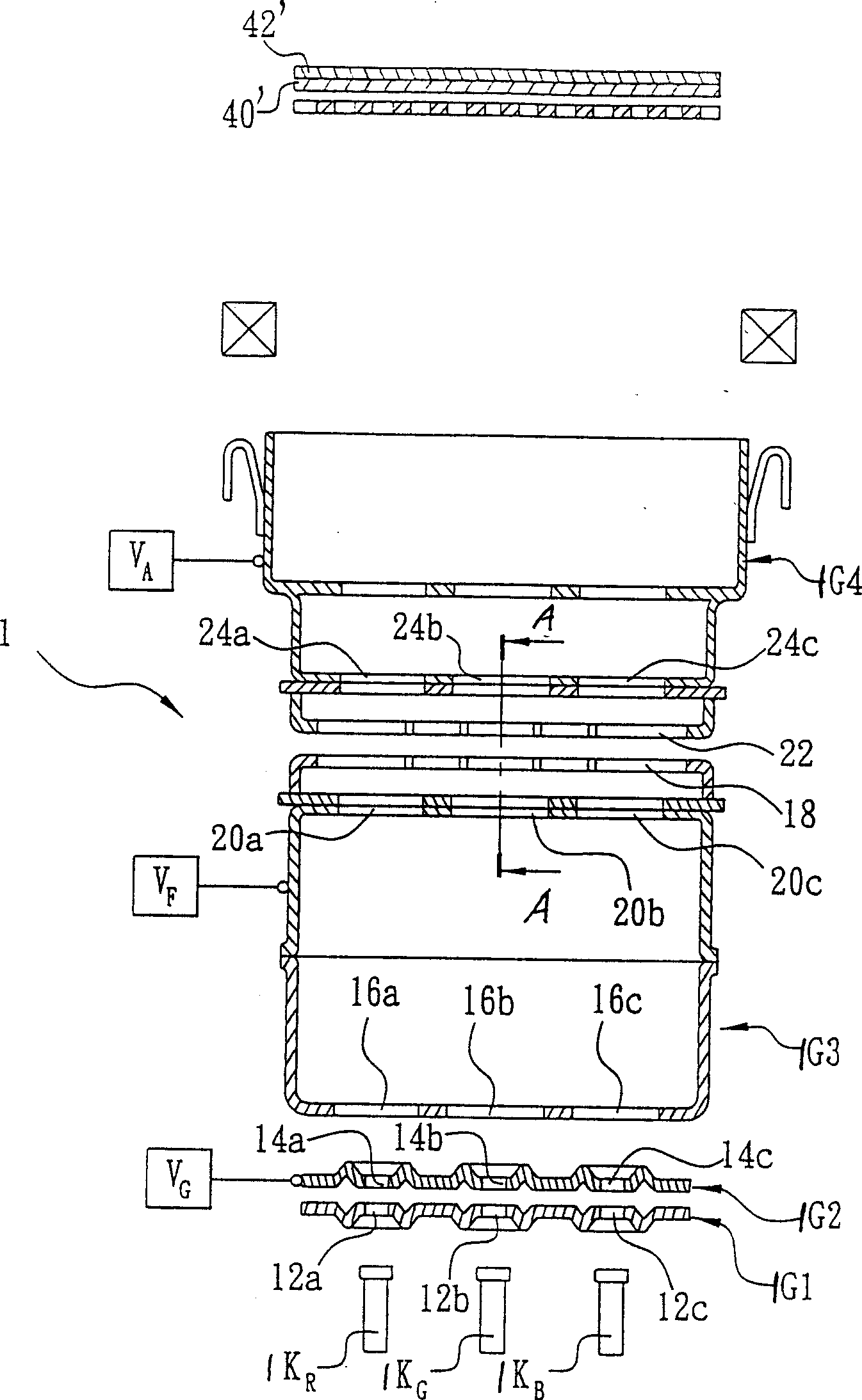
technical field [0001] The invention belongs to display components, in particular to an electron gun with a multi-layer common lens. Background technique [0002] Such as figure 1 Shown, the known electron gun 1 that is used in the color cathode ray tube (CRT), its energetic electron (electron) is by cathode (cathode) 1K R , 1K G , 1K B Emitted, and shoot to the electron beam forming region (Beam Forming Region) of electron gun 1, the electron beam forming region is composed of control electrode (control grid) 1G1, screen electrode (screen grid) 1G2, focusing grid 1G3 and grid 1G4 composition. [0003] Cathode (cathode) in cathode ray tube 1K R , 1K G , 1K B The energy-carrying electrons that can be generated can directly shoot to and pass through the pole holes 12a, 12b, 12c, 14a, 14b, 14c, 16a, 16b arranged in a straight line on the control electrode 1G1, screen electrode 1G2, and focusing grid 1G3. , 16c, and in the electron beam forming area, an electron beam wit...

Claims


Application Information

Patent Timeline
Patent Type & Authority Patents(China)
IPC IPC(8): H01J29/48H01J29/50
Inventor 陈兴耀
Owner CHUNGHWA PICTURE TUBES LTD
Learn More