
Method for realizing Ethernet passive optical fiber network

The technology of a passive optical fiber network and its implementation method is applied in the control field of broadband passive optical network transmission system, and can solve problems such as inability to segment Ethernet data packets, recombine, refine time slots, limit the application of EPON systems, etc., and achieve reduction The cost of network construction and the effect of initial investment and cost reduction

Inactive Publication Date: 2007-02-07
ZTE CORP
View PDF6 Cites 1 Cited by
  • Summary
  • Abstract
  • Description
  • Claims
  • Application Information

AI Technical Summary

Problems solved by technology

However, in this structural mode, the TDMA implementation of the EPON system is limited to a dedicated physical layer chip, and EPON users can only use a dedicated EPON physical layer chip to form a network, thus limiting the application of the EPON system
Since TDMA is implemented at the physical layer, Ethernet data packets from users cannot be re-segmented, reassembled, etc.
In the Ethernet PON (EPON) TDMA Interface in PHY Layer and other considerations proposal, there is no refinement of the time slot used for ranging

Method used


Image

  • Method for realizing Ethernet passive optical fiber network
  • Method for realizing Ethernet passive optical fiber network
  • Method for realizing Ethernet passive optical fiber network

Examples


Embodiment Construction

[0020] Below in conjunction with accompanying drawing, the implementation of the present invention is described in detail as follows:

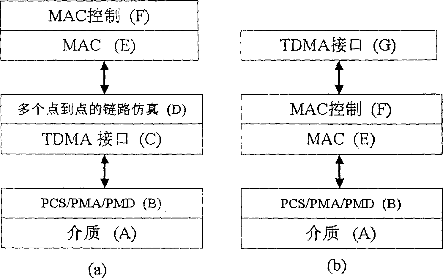
[0021] exist figure 1 Among them, (a) is the EPON layered structure mentioned in the proposal of IEEE 802.3 EFM Study Group in Ethernet PON (EPON) TDMA Interface inPHY Layer and other considerations, (b) is the EPON layered structure proposed in the present invention. Among them (A), (B) and (D) are the physical layer, (E) and (F) are the data link layer, (C) is TDMA integrated in the physical layer, (E) is established in the data link layer TDMA time slot allocation on the layer, which can complete the allocation of time slots, time-sharing transmission of data frames and related data link layer communications. PCS is the physical coding sublayer, PMD is the physical medium independent sublayer, and PMA is the physical medium additional sublayer.

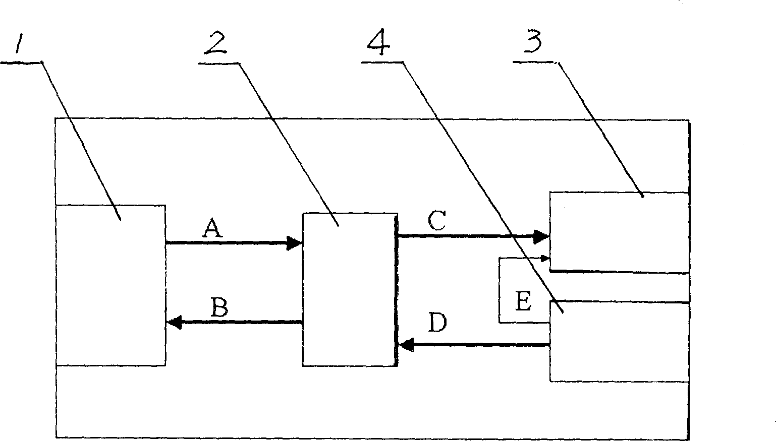
[0022] exist figure 2 Among them, A and B are the receiving and sending data lines from the...


PUM


Abstract

The method includes the step for allotting time slot by using OLT, ONU upward channel based on devices at current ONU end. Also the invention includes following steps. (1) TDMA treatment of Ethernet data packets is completed in MAC layer of upward channel through software by microcomputer, including the treatment of changing size of data packet as well as the operation that in the time period of transmitting and receiving corresponding data, the controller enables or closes pulsed light module in order to transmit or receive data of each ONU user. (2) Synchronous mark is sent through data frame in downward channel by OLT. Each ONU uses the synchronous mark to synchronize LT clock. (3) The first time slot after each synchronous mark in upward and downward data frame is fixed as the ranging time slot. (4) OLT and each ONU matching the said time slot completes the procedure for ranging a node.

Description

technical field [0001] The invention belongs to the category of optical fiber network transmission, in particular to a control method for a broadband passive optical network transmission system. Background technique [0002] At present, due to the rapid development of Internet services, network providers all over the world are doing their best to expand network capacity in order to welcome the arrival of the IP era. The capacity problem of the core network that has troubled for many years has been solved, and the cost ratio of the core network in the entire network has also dropped significantly. However, the bottleneck of capacity and cost is once again pushed to the transmission part of the access network. Today, the problem that plagues telecom operators is mainly how to deal with the rapid development of Internet broadband access requirements and the aggressive competition of competitors. Therefore, they need to increase communication cap...

Claims


Application Information

Patent Timeline
Patent Type & Authority Patents(China)
IPC IPC(8): H04B10/12H04B10/25H04Q11/00
Inventor 沈瑞武晏祥彪郭莉
Owner ZTE CORP
Learn More