Clear liquid disturbanceless spiral discharging settling centrifugal machine

A settling centrifuge and screw unloading technology, applied in centrifuges, centrifuges with rotating drums, etc., can solve the problems of limited application range, achieve a wide range, improve the separation capacity of a single machine, and increase the settling area Effect

Inactive Publication Date: 2007-03-07
SICHUAN UNIV
View PDF5 Cites 0 Cited by
  • Summary
  • Abstract
  • Description
  • Claims
  • Application Information

AI Technical Summary

Problems solved by technology

However, this technology does not completely solve the problem of the disturbance of the spiral blade to the clarified liquid layer in the drum settling section, but only reduces the disturbance and its influence on the settlement, that is, it does not fundamentally eliminate the impact of the disturbance on the clarity of the clarified liquid. Impact
Therefore, the suspension separation that is difficult to separate and requires a particularly high clarity of the clarified liquid still cannot meet the requirements, and the scope of application is still limited.

Method used


Image

  • Clear liquid disturbanceless spiral discharging settling centrifugal machine
  • Clear liquid disturbanceless spiral discharging settling centrifugal machine

Examples


Embodiment 1

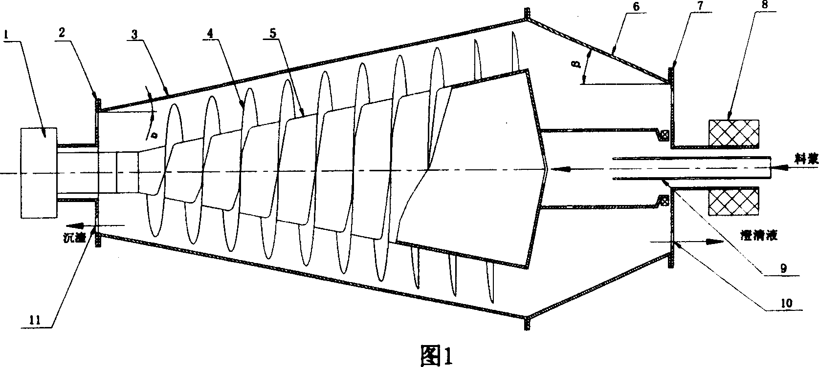
[0021] The structure is shown in Figure 1. The drum is composed of a spiral slag discharge section 3 and a clarified liquid overflow section 6. Both the spiral slag discharge section and the clarified liquid overflow section have a conical structure. The angle α is 10°, and the half-cone angle β of the cone in the clarified liquid overflow section is 40°. The drum is placed on the frame and driven by the motor through the belt pulley 8 transmission mechanism. The screw conveyor located in the drum, the part corresponding to the spiral slag discharge section of the drum, the spiral blade 4 and the cylinder body 5 where the blade is installed are basically the same as the cone cylinder half-cone angle α of the spiral slag discharge section of the drum conical structure. The part of the cylinder of the screw conveyor corresponding to the clarified liquid overflow section 6 of the bowl has a cylindrical structure, and no helical blade is arranged on it; the differential 1 is arran...

Embodiment 2

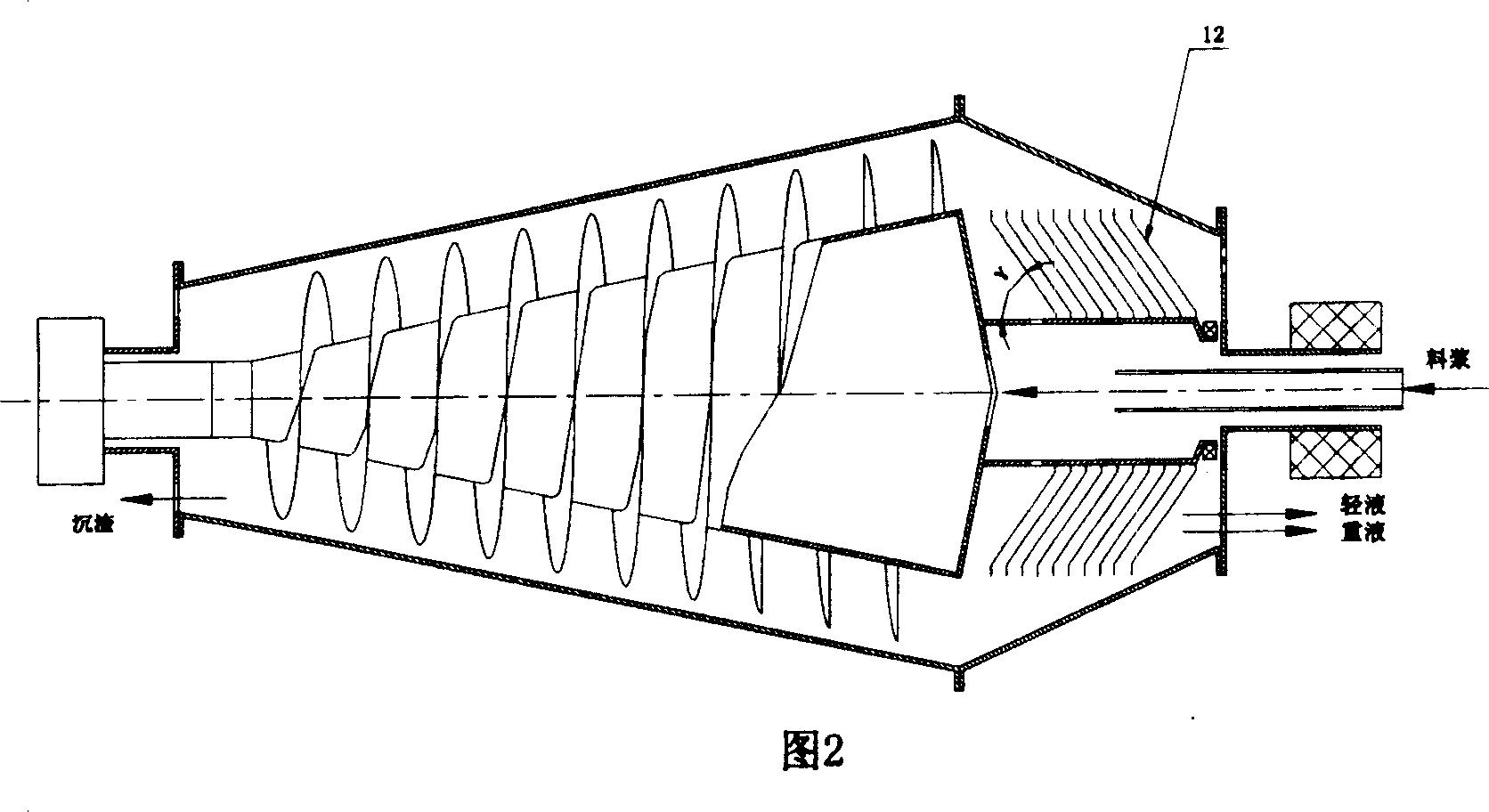
[0024] The specific structure is shown in Figure 2. The other structures of this embodiment are the same as those of Embodiment 1, except that a group of discs 12 that increase the settling area are arranged in the clarified liquid overflow section of the drum, and the discs are arranged on the barrel of the screw conveyor. . The direction of the half-cone angle γ of the disc is the same as that of the cone in the clarified liquid overflow section of the bowl.


PUM


Abstract

A centrifugal machine for clarifying liquid technically features that its drum-type overflow segment of clarified liquid has a hollow conic structure, the part of spiral conveyer, which is relative to said overflow segment, has no spiral blade, and the dregs are centrifugally pushed toward the dregs discharge segment and then are delivered to dregs outlet by spiral blades.

Description

1. Technical field [0001] The present invention relates to a spiral discharge sedimentation centrifuge, more specifically relates to a spiral discharge sedimentation centrifuge which is difficult to separate materials and requires higher clarity for clarified liquid, which can be applied to liquid-solid phase separation, and is also suitable for Liquid-liquid-solid phase separation. 2. Background technology [0002] The screw discharge sedimentation centrifuge is a kind of solid-liquid separation equipment that utilizes the difference in solid-liquid density to make the solid phase settle rapidly under the action of centrifugal force, and the sediment is transported to the outside of the machine by the screw. It is widely used in industrial production and sewage treatment. It is especially suitable for solid-liquid separation of suspensions with small solid particle size and difficult to separate by filtration. The screw discharge decanter centrifuge mainly includes a drum ...

Claims


Application Information

Patent Timeline
Patent Type & Authority Patents(China)
IPC IPC(8): B04B1/20B04B7/08
Inventor 梁明征钟月华伍勇肖泽仪
Owner SICHUAN UNIV
Why Eureka
Try Eureka