Rotary drum type sterilized filling device

A technology of filling device and drum, which is applied in liquid filling, packaging, bottling machines, etc., and can solve problems such as working environment pollution

Inactive Publication Date: 2007-03-07
SHIKOKU KAKOOKI CO LTD
View PDF3 Cites 2 Cited by
  • Summary
  • Abstract
  • Description
  • Claims
  • Application Information

AI Technical Summary

Problems solved by technology

In the above-mentioned filling device, the sterilizing liquid, gas, etc. are also discharged to the atmosphere through the exhaust flow path like the sterile air, which is the main cause of the pollution of the working environment.

Method used


Image

  • Rotary drum type sterilized filling device
  • Rotary drum type sterilized filling device
  • Rotary drum type sterilized filling device

Examples


Embodiment Construction

[0024] The following description will be made with reference to the embodiments of the present invention.

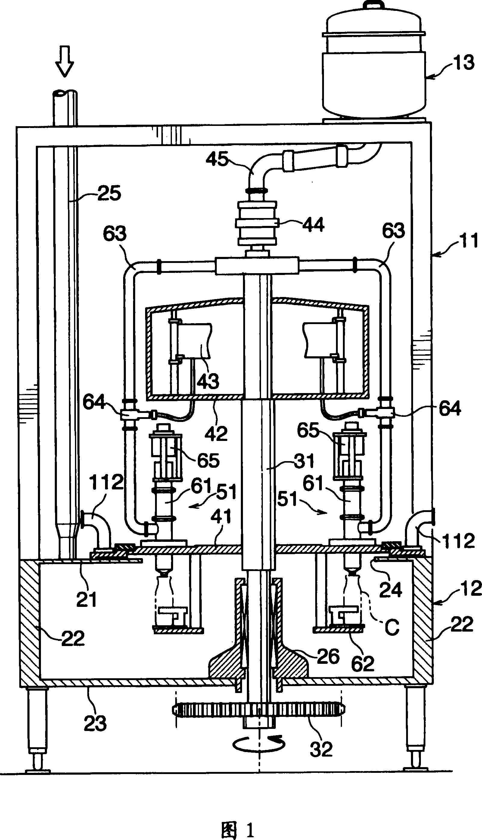
[0025] The filling device has a device main body 11 with a skeleton structure, a sterile chamber 12 arranged at the bottom of the device main body 11 and a filling liquid tank 13 supported on the top of the device main body 11 .

[0026] The sterile room 12 is viewed as a square box from above, and has a top wall 21 , a side wall 22 and a bottom wall 23 . A circular opening 24 is provided at the center of the top wall 21 . A sterile air supply pipe 25 is connected to the side of the opening 24 . A bearing 26 is provided on the bottom wall 23 , and the bearing 26 is concentric with the center of the opening 24 .

[0027] The bearing 26 is supported by the vertical rotation shaft 31 . The rotation shaft 31 longitudinally cuts off the sterile chamber 12 , and its upper end reaches near the top of the device main body 11 . A driven gear 32 that meshes with a not-shown dr...


PUM


Abstract

An aseptic filling apparatus of the rotary type comprises an aseptic chamber 12 provided for surrounding a path of transport of containers along with a turntable 41. An air discharge channel 71 is provided between the turntable 41 and the aseptic chamber 12. A channel control member 81 is fixedly disposed so as to cover the air discharge channel 71, and to be opposed to the turntable 41 and the aseptic chamber 12 with the channel 71 positioned therebetween. Seal clearances 101, 102 are formed between the turntable 41 and the channel control member 81, and a vent clearance 92 is provided between the aseptic chamber 12 and the channel control member 81. A collection pipe 112 is in communication with the vent clearance 92.

Description

technical field [0001] The present invention relates to a drum-type aseptic filling device for filling beverages and the like into containers under aseptic conditions. Background technique [0002] Such a filling device is known in the prior art as disclosed in Japanese Patent Publication No. JP-A3-29703, which has a turntable, a plurality of filling nozzles, a container seat and a sterile chamber, wherein the discharge ports of the filling nozzles are directed downwards Installed on the periphery of the turntable, the container seat is set to rotate synchronously with the turntable, and corresponds to each filling nozzle to accept the container during filling. The aseptic room is designed to surround the moving path of the container together with the turntable, and the exhaust flow path is formed on the turntable and without Between the bacteria chambers, it communicates with the atmosphere. [0003] When the above-mentioned filling device is stably filling, the aseptic ch...

Claims


Application Information

Patent Timeline
Patent Type & Authority Patents(China)
IPC IPC(8): B65B3/00B65B55/02B65B55/10B67C3/02B67C3/22B67C3/26B67C7/00F16J15/447
CPCB67C3/22B67C2003/2694B67C2003/228B67C7/0073B67C3/02
Inventor 田和茂宣御船正三木隆雄植田道雄
Owner SHIKOKU KAKOOKI CO LTD
Why Eureka
Try Eureka