
Electrical control fluid flow adjusting device

A technology of adjusting device and fluid flow, applied in the field of pressurization speed control, depressurization and exhaust device, can solve the problems of cumbersome production process, power consumption, inability to magnetic shield, etc., to simplify the number of product parts and processing technology, reduce Hysteresis and kinematic friction, ease of design and effects of miniaturization

Inactive Publication Date: 2007-03-21
SHENZHEN KINGYIELD TECH
View PDF8 Cites 0 Cited by
  • Summary
  • Abstract
  • Description
  • Claims
  • Application Information

AI Technical Summary

Problems solved by technology

[0008] 1. All the above-mentioned patented products are considered to have too many parts and the structure is too complicated
[0009] 2. Due to too many parts, the production process is cumbersome, and the quality control is more difficult and the production cost is expensive
[0010] 3. Due to too many parts, its reliability is greatly reduced, resulting in a reduction in its service life
[0011] 4. Due to too many parts, it is difficult to realize the miniaturization of its product design
[0012] 5. The shell design of all the above patents is plastic and cannot be magnetically shielded
The eddy current generated by the coil and the iron core not only consumes electric energy and reduces the efficiency of the product, but also increases the temperature and heat of the product, which seriously affects the normal operation of the product, reduces the reliability of circuit control and increases the power consumption of the product
[0013] 6. All the above-mentioned patented products and electronic control circuits of the products are designed separately, which is not conducive to the control of product quality, increases the cost of the product, and greatly reduces the reliability of the product

Method used


Image

  • Electrical control fluid flow adjusting device
  • Electrical control fluid flow adjusting device
  • Electrical control fluid flow adjusting device

Examples


Embodiment Construction

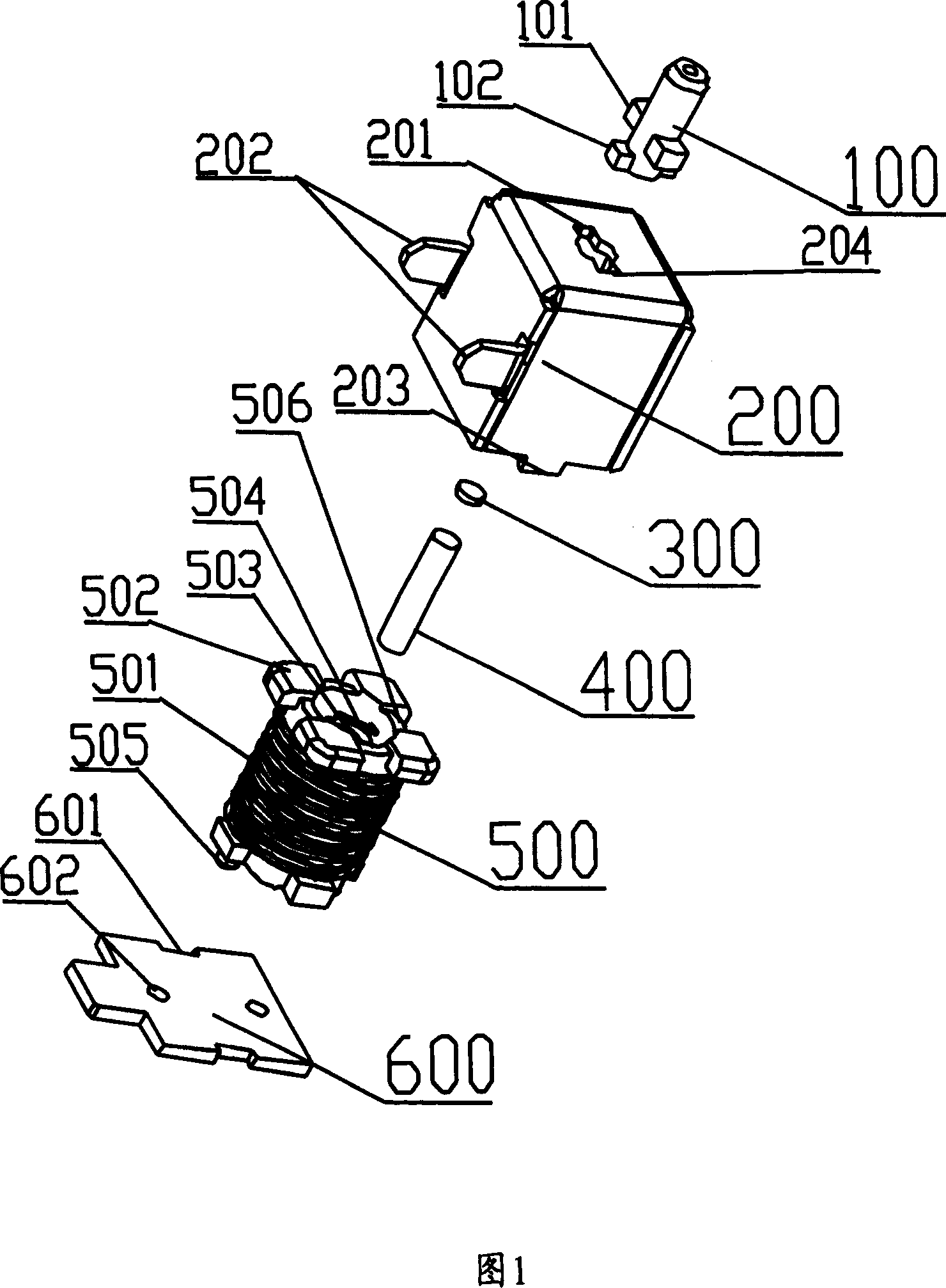
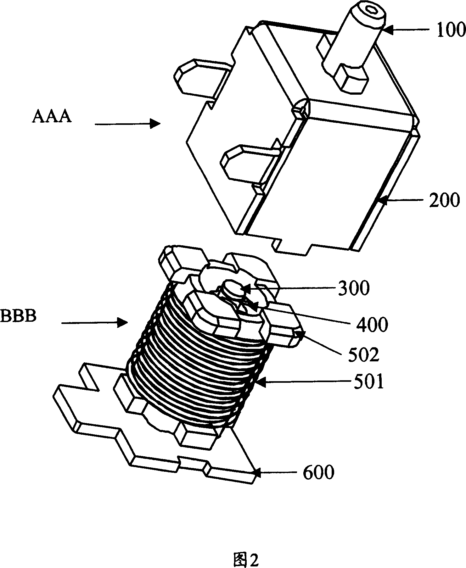
[0040] With reference to Figures 1 to 5, an electronically controlled fluid flow regulating device is composed of an electronically controlled component BBB and a shielding component AAA. The shielding assembly AAA includes a casing 200, and the electronic control assembly BBB includes an electronically controlled valve body installed in the casing 200 and a control circuit board 600 that controls the action of the electronically controlled valve body to open / close the air nozzle 100 disposed on the casing. in:

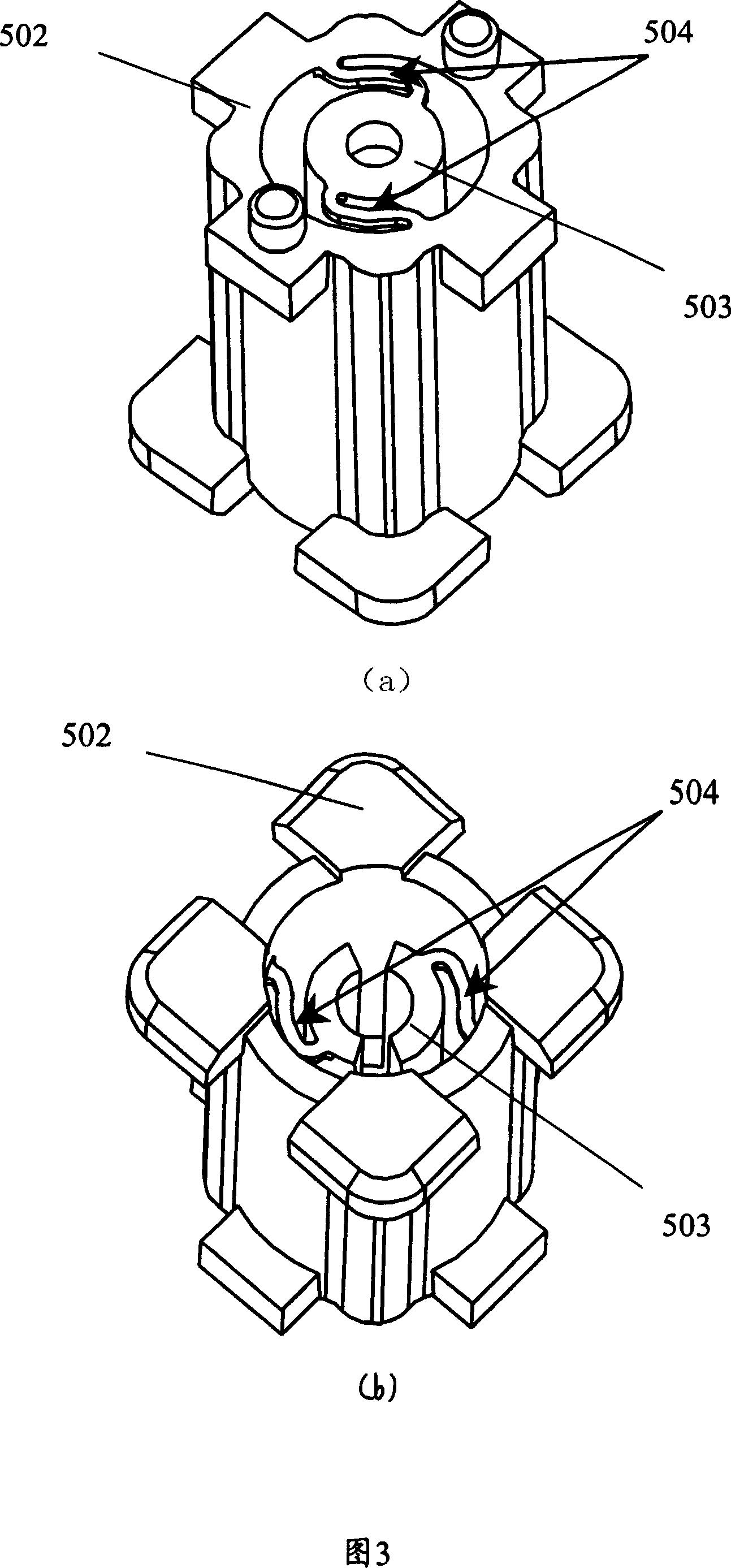
[0041] The electronically controlled valve body 500 includes a coil 501, a skeleton 502, a magnetic core rod bracket 503, an elastic arm 504 and a magnetic core rod 400. The magnetic core rod bracket 503 in the center of the skeleton 502 is connected to the skeleton 502 through two elastic arms 504 designed at both ends. As a whole, a quantitative coil 501 is wound around the skeleton 502, and at the same time, the air plug 300 with glue or adhesive tape attached to o...


PUM


Abstract

One kind of rate of fluid flow adjusting device, including the outer covering, installs in the outer covering the electrically controlled valve body and the control electrically controlled valve body movement control circuit board, states the electrically controlled valve body to include the coil, the skeleton, the magnetic core good support, the ball arm of force and the magnetic core stick, outside the skeleton circles the coil, the coil causes the welding control circuit board, for the skeleton center magnetic core good support through two designs balls arm of force with the skeleton company is a body, a magnetic core stick end loads fixes on the magnetic core good support, the magnetic core stick another end surface pastes is useful coats the idle talk to the control electromagnetic screen to open / shutting down gas bag, The outer covering is the electromagnetism screening can, the control circuit board surface has the shield level, on the electrically controlled valve body fixed once more control circuit board, has the electromagnetism screening can and the seal electromagnetic screen gap control circuit board permanent connection constitution electromagnetism entire screening can. Uses this invention, screening can eliminated the electronmagetic interference through the electromagnetism, the electric circuit control section and the product design is a body, big simplified the product zero number of articles, reduced the production cost, is the production is easier to manage the control, makes the product reliability greatly to enhance.

Description

【Technical field】 [0001] The present invention relates to a fluid flow regulating device, in particular to a depressurizing and exhausting device used in an electronic sphygmomanometer, which is also particularly suitable for the control of the pressurizing speed of the pressurized sphygmomanometer. 【Background technique】 [0002] Commonly used fluid flow regulating devices have extremely complex structures, cumbersome processes, high manufacturing costs, and inconvenience in production and quality control. [0003] The name of the invention announced in the Japanese Patent Office is: pressure regulating valve unit and its automatic sphygmomanometer; Patent No. 2000-346230. Among them, there are more than 11 parts; [0004] The name of the invention announced in the Japanese Patent Office is: "Fluid flow regulating device, namely, exhaust device for sphygmomanometer and sphygmomanometer", the invention patent of Laid-Open Patent No. 2002-108456A, which has more than 14 part...

Claims


Application Information

Patent Timeline
Patent Type & Authority Patents(China)
IPC IPC(8): F16K31/06A61B5/0235F16K1/00
Inventor 章年平
Owner SHENZHEN KINGYIELD TECH
Learn More