Control system, method, and program using rhythm pattern

A control system and rhythm technology, applied in the direction of mechanical mode conversion, data processing input/output process, user/computer interaction input/output, etc., can solve the problems of voice recognition rate reduction and lack of voice recognition speed, etc. achieve good operability

Inactive Publication Date: 2007-03-21
PANASONIC CORP
View PDF4 Cites 0 Cited by
  • Summary
  • Abstract
  • Description
  • Claims
  • Application Information

AI Technical Summary

Problems solved by technology

[0007] The problem with the system using voice recognition is that the voice recognition rate decreases depending on the surrounding conditions such as surrounding noise, background music, speaker's voice, and the position of the microphone.
In this way, in a system with insufficient memory or calculation speed, there is a problem that a practical voice recognition speed cannot be obtained.

Method used


Image

  • Control system, method, and program using rhythm pattern
  • Control system, method, and program using rhythm pattern
  • Control system, method, and program using rhythm pattern

Examples


no. 1 Embodiment approach

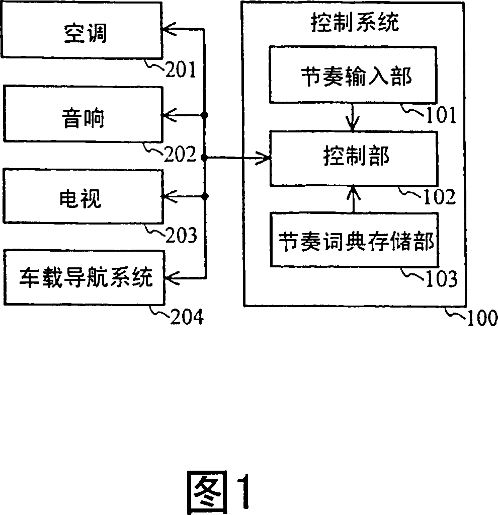
[0124] FIG. 1 shows the configuration of a control system 100 according to the first embodiment of the present invention and the overall configuration of a system using the control system. In the present embodiment, for easy understanding of the description, the control system 100 is a system for controlling devices such as an air conditioner and an audio system in a vehicle.

[0125] In FIG. 1 , the system as a whole includes a control system 100 , an air conditioner 201 , a stereo 202 , a TV 203 and a car navigation system 204 . The air conditioner 201, the audio system 202, the television 203, and the car navigation system 204 are devices installed in the vehicle (hereinafter referred to as in-vehicle devices). The in-vehicle device shown here is an example. Devices other than the in-vehicle devices shown in FIG. 1 may also be provided in the system. Only some of the in-vehicle devices shown in FIG. 1 may be provided in the system.

[0126] The control system 100 include...

no. 2 Embodiment approach

[0164] The overall system configuration of the second embodiment of the present invention is the same as that of the first embodiment, so FIG. 1 is used in the second embodiment. The following description will focus on differences from the first embodiment.

[0165] The rhythm input unit 101 of the second embodiment is constituted by an analog input device such as a piezoelectric sensor.

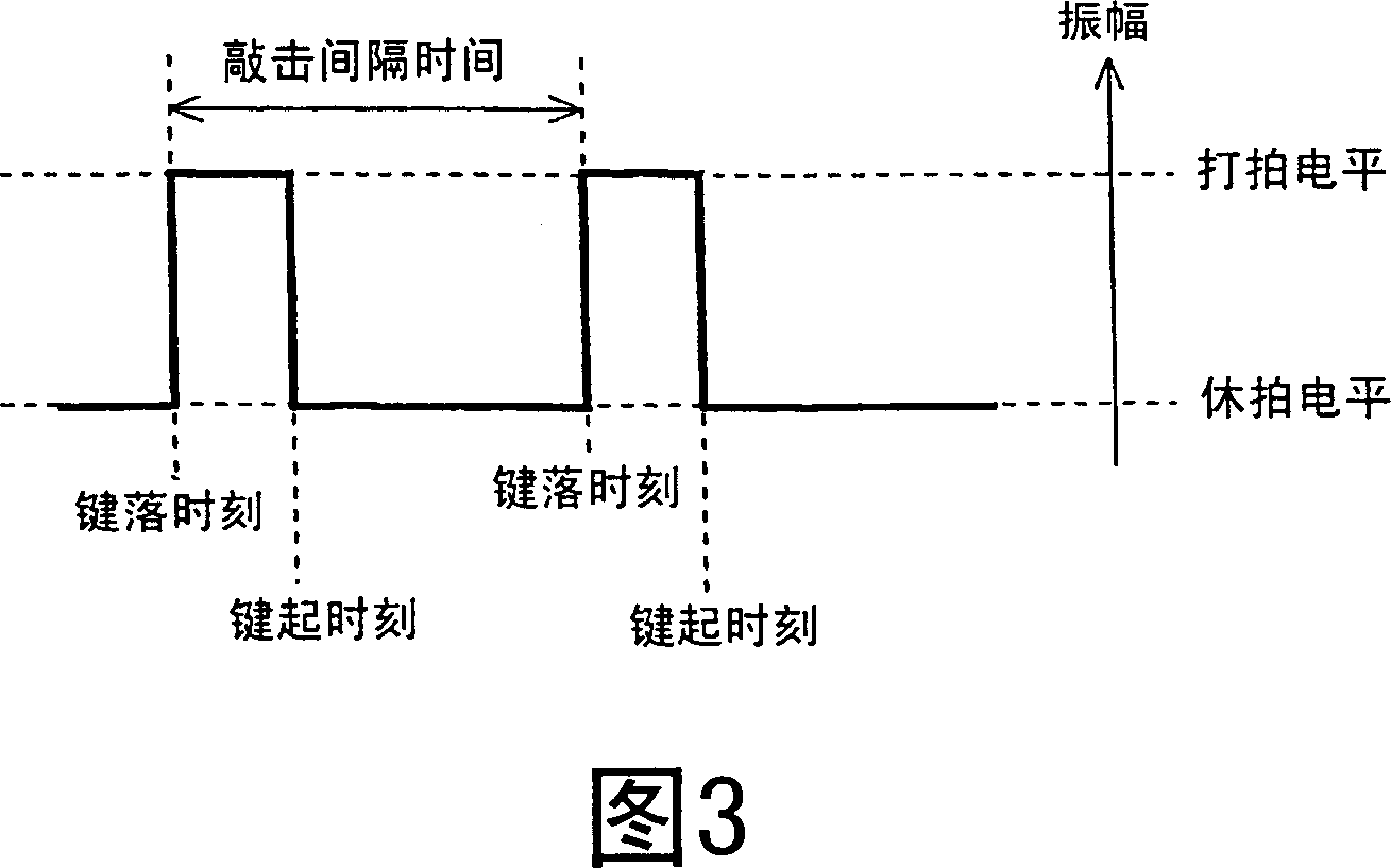
[0166] FIG. 10 is a schematic diagram showing a rhythm pattern signal waveform output from the rhythm input unit 101 of the second embodiment. In the second embodiment, the downbeat and downbeat levels are set in advance. The rhythm input unit 101 is an analog input device, so as shown in FIG. 10 , the amplitude level of the input signal changes according to the strength of the user's tap. In the second embodiment, the peak time when the amplitude level of the waveform exceeds the downbeat or downbeat level is called the key-down time, and the time when the amplitude level becomes the lowe...

no. 3 Embodiment approach

[0185] The overall system configuration of the third embodiment of the present invention is the same as that of the first embodiment, so FIG. 1 is used in the third embodiment. The rhythm input unit 101 of the third embodiment may be a digital input device or an analog input device.

[0186] The operation of the control unit 102 in the third embodiment will be described below. The operation of the main program of the control unit 102 when the user inputs a rhythm is the same as that of the first embodiment, so FIG. 6 is used. In the third embodiment, input rhythm pattern recognition processing is different from that in the first embodiment.

[0187] FIG. 14 is a flowchart showing the detailed operation of the control unit 102 of the third embodiment in the input rhythm pattern recognition process. The operation of the control unit 102 in the input rhythm pattern recognition process will be described below with reference to FIG. 14 .

[0188] First, after the control unit 10...


PUM


Abstract

A control system for reliably performing minimally required operations using a small number of input devices is provided. A rhythm input section ( 101 ) converts a rhythm pattern input by the user to an electrical signal, which is in turn output. A rhythm dictionary storage section ( 103 ) stores a rhythm dictionary table which associates the contents of a control of an apparatus with a registered rhythm pattern. The registered rhythm pattern is obtained by typifying a pronunciation pattern of a name indicating the contents of the control. A control section ( 102 ) analyzes the electrical signal from the rhythm input section ( 101 ) to recognize the input rhythm pattern input by the user, recognizes the contents of a corresponding control by referencing the rhythm dictionary storage section ( 103 ), and controls an operation of an in-vehicle apparatus.

Description

technical field [0001] The present invention relates to a system for controlling the actions of various devices, and more particularly to a system for providing a user interface for controlling the actions of various devices with a small number of operating devices. Background technique [0002] Today's various devices, especially audio-visual equipment such as televisions, video recorders, and stereos, and vehicle-mounted equipment such as car navigation systems and car audio systems, have many functions. Accordingly, the number of operating devices such as keys and joysticks mounted on the main body of the device or the remote controller has also increased. The addition of operating equipment complicates and complicates operations. [0003] In addition, it is also difficult to arrange input devices corresponding to dozens or hundreds of functions in a limited space. [0004] In order to solve the above problems, various systems have been proposed. For example, a system ...

Claims


Application Information

Patent Timeline
Patent Type & Authority Patents(China)
IPC IPC(8): G06F3/023G06F3/00G06F3/01
CPCG06F3/011G06F3/023
Inventor 山下敦士阪本清美饭阪笃
Owner PANASONIC CORP
Why Eureka
Try Eureka