Flow controller

A technology of flow control device and fluid passage, applied in the direction of flow control, non-electric variable control, valve device, etc., can solve the problems of vibration and noise, and achieve the effect of simple structure

Inactive Publication Date: 2007-04-04
SANKYO SEIKI MFG CO LTD
View PDF5 Cites 0 Cited by
  • Summary
  • Abstract
  • Description
  • Claims
  • Application Information

AI Technical Summary

Problems solved by technology

[0003] However, the electromagnet is repeatedly turned on and off for valve opening and closing control, so it is necessary to perform frequent on and off operations for high-precision flow control, resulting in a problem of noise.
In addition, as a problem inherent in the electromagnet itself, vibration may sometimes occur, and if it is in this state, it is impossible to perform high-precision control

Method used


Image

  • Flow controller
  • Flow controller
  • Flow controller

Examples


Embodiment Construction

[0022] Hereinafter, the flow control device to which the present invention is applied will be described with reference to the drawings.

[0023] [the whole frame]

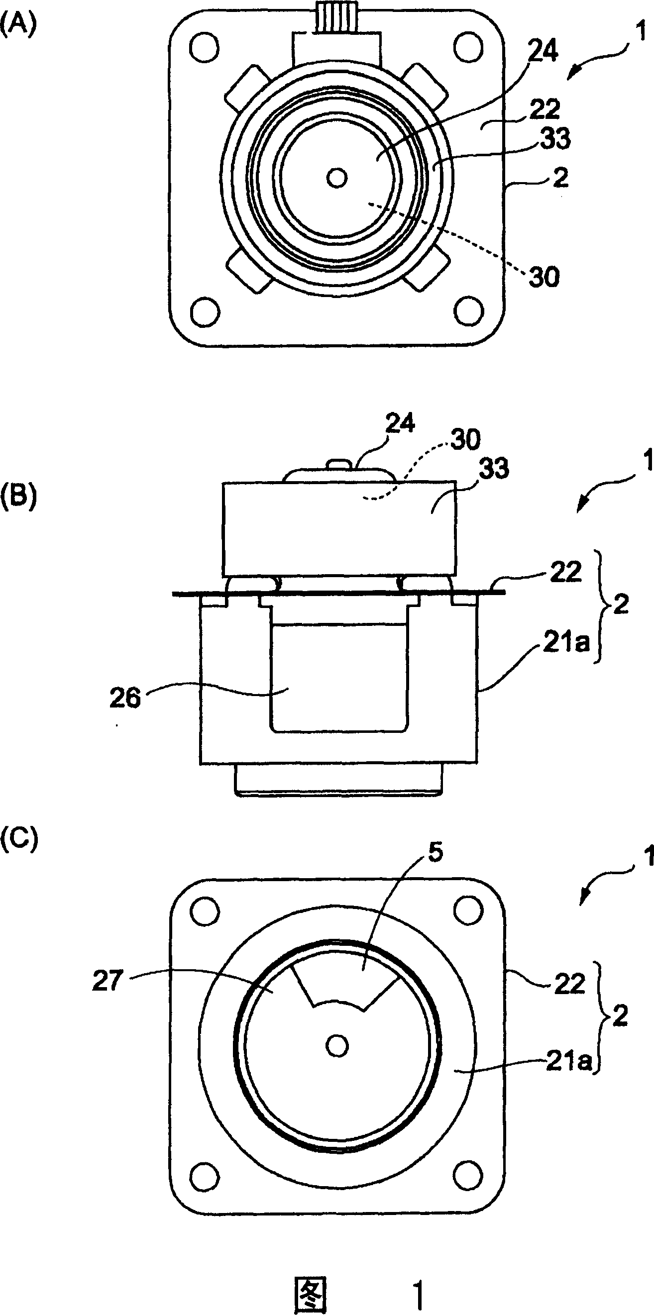
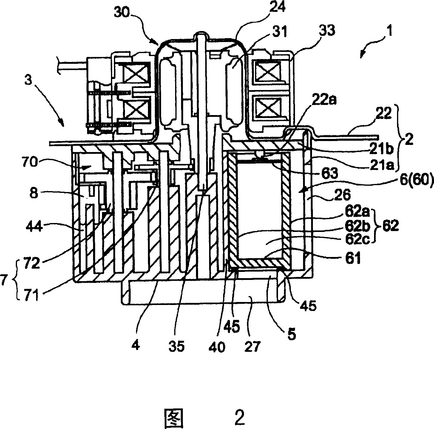
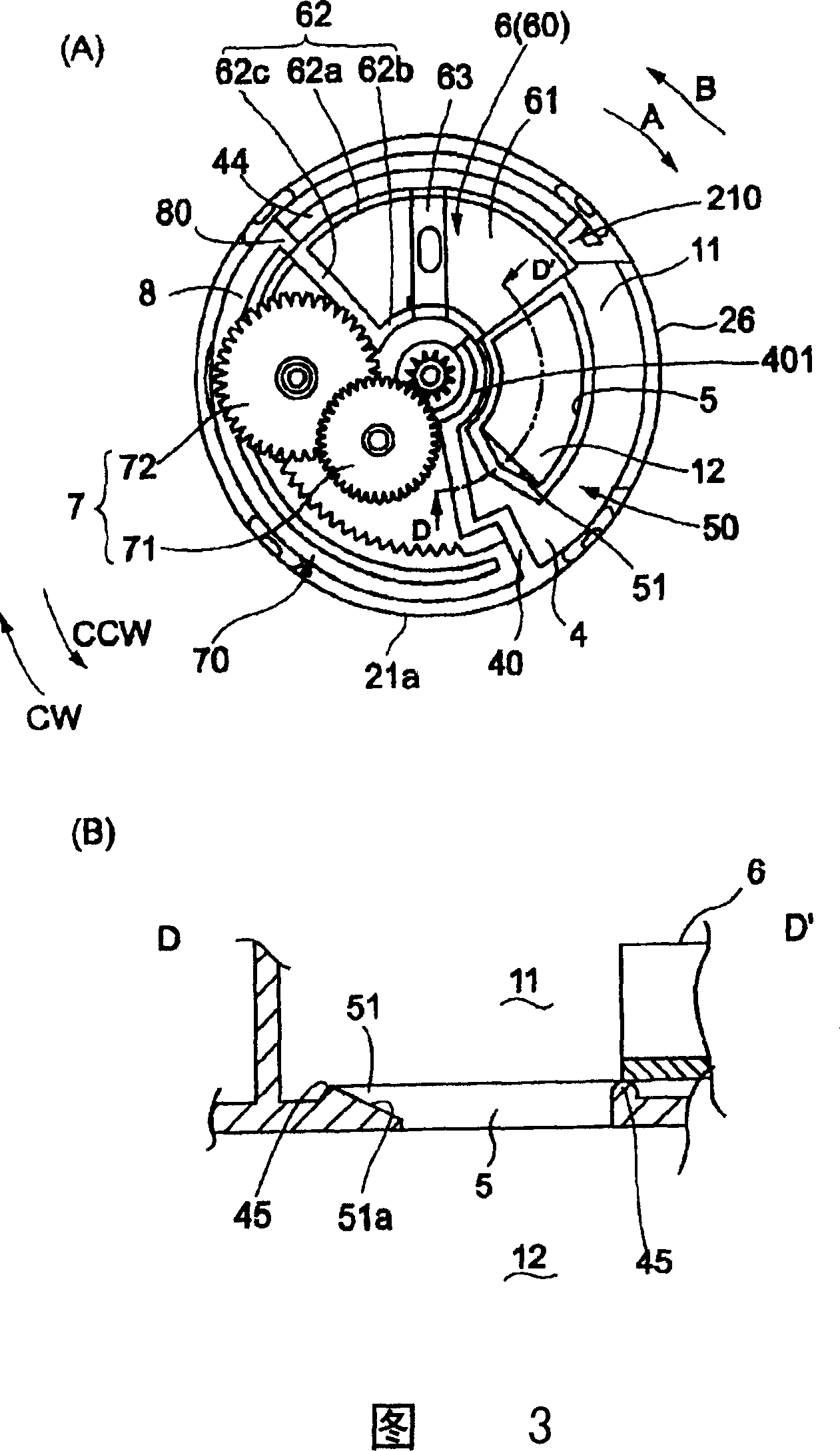
[0024] Fig. 1 (A), (B), (C) are respectively a plan view, a front view and a bottom view of a flow control device to which the present invention is applied. Fig. 2 is an expanded view of a gear set and the like arranged in a housing of a flow control device to which the present invention is applied. 3(A) and (B) are respectively a plan view and a D-D' cross-sectional view showing the opened state of the valve body in the housing of the flow control device to which the present invention is applied. 4(A) and (B) are respectively a plan view and an E-E' cross-sectional view showing the closed state of the valve body in the housing of the flow control device to which the present invention is applied.

[0025] In Figure 1 (A), (B), (C) and Figure 2, the flow control device 1 applying the present invention is used to control...


PUM


Abstract

PURPOSE: A flow control system is provided to prevent noise or chattering, to regulate the opening degree by covering an opening unit by a valve body with sliding along a partition, and to change a flow control pattern by changing the shape of the opening unit, instead of the shape of a valve. CONSTITUTION: A flow control system(1) embeds a partition(4) for dividing a fluid passage, a valve for regulating the opening degree of an opening unit(5) formed on the partition, and a valve driving device(3) for operating the valve in a case. The valve driving device comprises a motor(30) supplied as a driving source and a transmission mechanism(7) for transmitting the output of the motor to a valve body(6) and rotating and moving the valve within a predetermined range. The valve body rotatively moves with sliding for the partition to regulate the opening degree of the opening unit.

Description

Technical field [0001] The present invention relates to a flow control device for controlling the flow of various fluids, and more particularly to a valve mechanism of the flow control device. Background technique [0002] The valve mechanism used in flow control devices that control the flow of LP gas, city gas, refrigerant, or liquid in refrigerators and air conditioners usually uses an electromagnet to drive the valve body. [0003] However, since the electromagnet repeatedly performs on and off valve opening and closing control, frequent on and off operations are required for high-precision flow control. As a result, there is a problem of noise. In addition, as an inherent problem of the electromagnet itself, vibration may sometimes occur. If it is in this state, it is impossible to perform high-precision control. Summary of the invention [0004] In view of the above problems, the subject of the present invention is to provide a flow control device that can achieve high-pre...

Claims


Application Information

Patent Timeline
Patent Type & Authority Patents(China)
IPC IPC(8): F16K3/04F16K31/04
CPCG05D7/0635A47L15/0049A47L15/4285A47L15/488A47L2501/10
Inventor 则武诚一朗
Owner SANKYO SEIKI MFG CO LTD
Why Eureka
Try Eureka