Magnetic suspension track inspection railcar

A technology of maglev track and inspection vehicle, which is applied to railway inspection vehicles and other directions, and can solve problems such as inappropriateness and inability to drive

Inactive Publication Date: 2007-04-11
TONGJI UNIV +1
View PDF11 Cites 1 Cited by
  • Summary
  • Abstract
  • Description
  • Claims
  • Application Information

AI Technical Summary

Problems solved by technology

[0003] The purpose of the present invention is to overcome the deficiencies in the prior art and provide a maglev track inspection car, which can solve the problem that the wheels, axles and bogies in the running part of the rail car in the prior art are completely unsuitable for maglev high-speed trains. The upper structure of the special maglev track beam, an

Method used


Image

  • Magnetic suspension track inspection railcar
  • Magnetic suspension track inspection railcar
  • Magnetic suspension track inspection railcar

Examples


Embodiment Construction

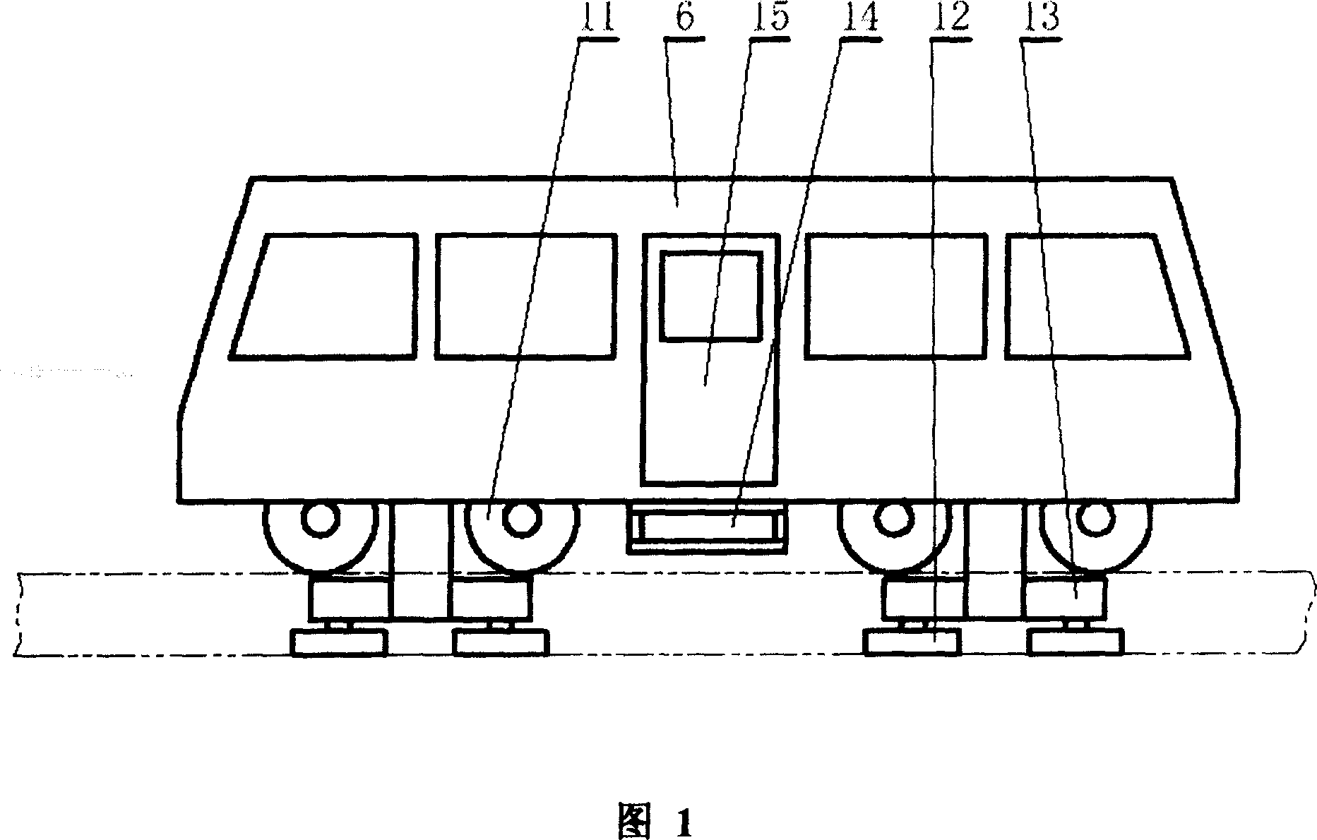
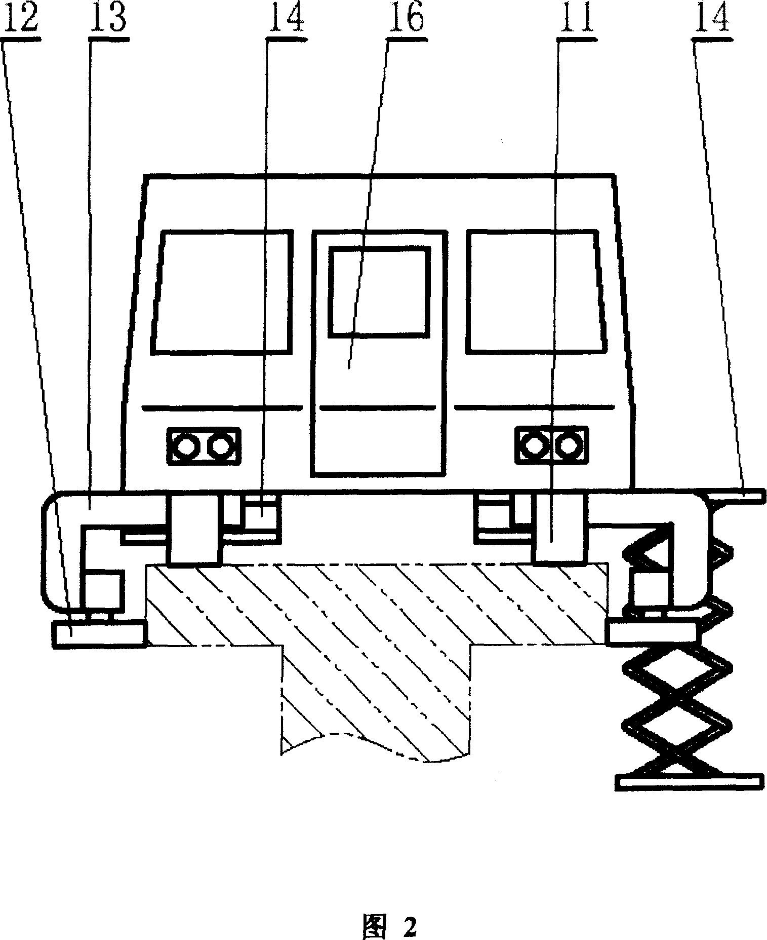
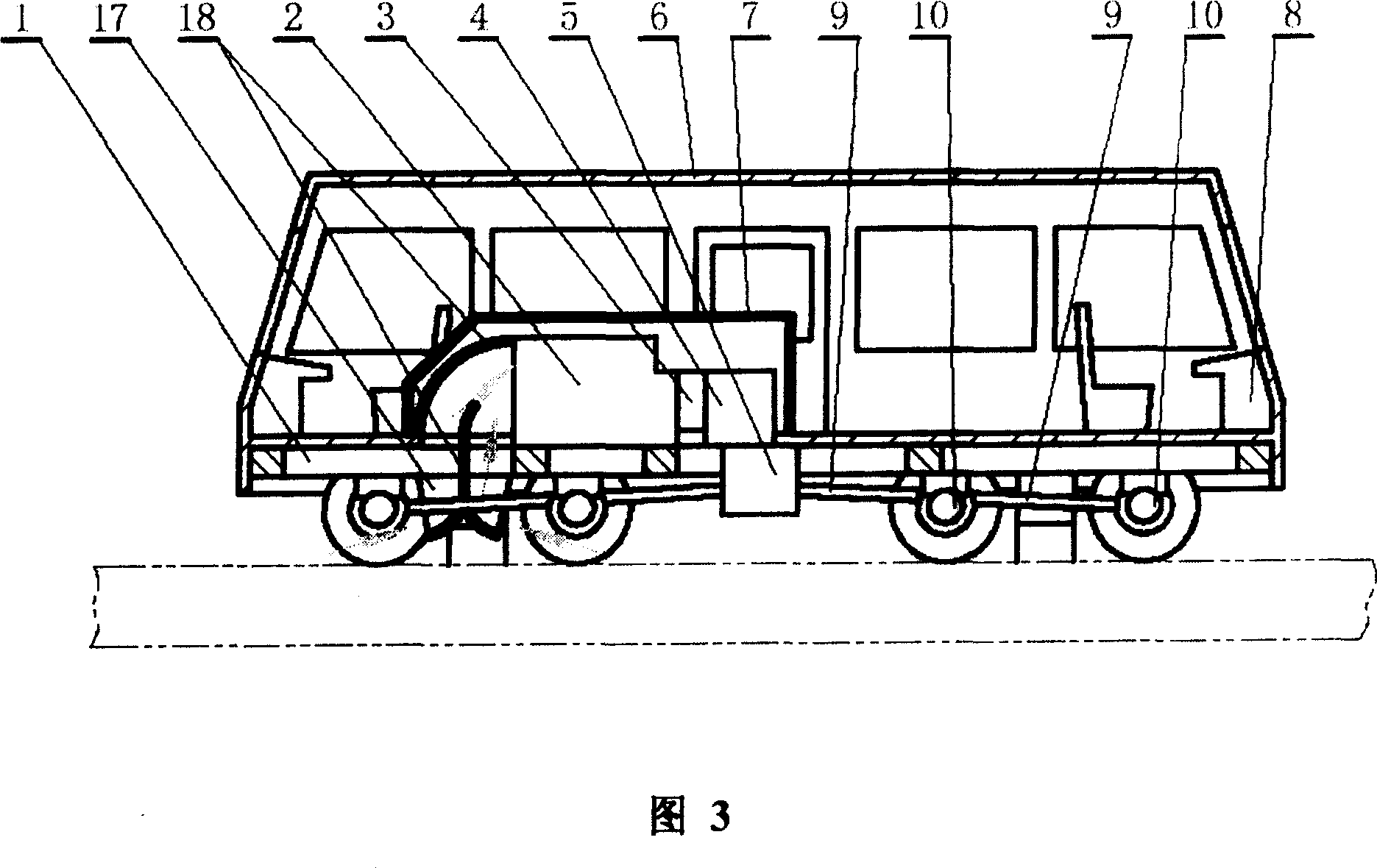
[0013] As shown in Fig. 1, Fig. 2 and Fig. 3, the present invention includes: vehicle frame 1, engine 2, hydraulic torque converter 3, gearbox 4, inter-axle differential 5, vehicle body 6, engine cover 7, instrument console 8. Universal joint 9, drive axle 10, rubber tire wheel 11, lateral guide wheel 12, guide wheel frame 13, maintenance elevator 14. The connection method is: the engine 2 and the gearbox 4 are fixed in the body 6 on the frame 1, the torque converter 3 is connected to the output end of the engine 2, and the gearbox 4 is connected to the output end of the torque converter 3 , the inter-axle differential 5 is connected to the output end of the gearbox 4, and the two output ends of the inter-axle differential 5 are respectively connected to two through joints arranged in the middle under the frame 1 and the body 6 through universal joints 9 Type driving axle 10, these two through-type driving axles 10 are respectively connected through two universal joints 9 to b...


PUM


Abstract

A running detection vehicle for magnetic levitation railway is composed of vehicle frame, vehicle body, engine, speed variator, differential gear between axles, meter panel, universal joint, drive bridge, wheels, lateral guide wheel, and lifting stepladder for maintenance.

Description

technical field [0001] The invention relates to a rail inspection engineering vehicle, in particular to a maglev rail inspection vehicle used for inspection, traction and maintenance of a maglev high-speed train rail system. It belongs to the field of rail transit engineering. Background technique [0002] At present, the track engineering vehicles used for inspection, traction, maintenance and overhaul of rail transit, that is, railways, high-speed railways, quasi-high-speed railways and suburban light rail railways, can be used for two-way traction and driving on railway rails, and are guided by rails. The small internal combustion engine-driven vehicles have the same characteristics as the vehicles running on various railways, using steel wheels suitable for the cross-section of the rails, as well as special axles and bogies for railways; and the sleeper system structure of the maglev high-speed train The form is completely different. It has no two rails with "I"-shaped ...

Claims


Application Information

Patent Timeline
IPC IPC(8): B61D15/08
Inventor 张建武顾力强何大海黄宏成李进军
Owner TONGJI UNIV
Why Eureka
Try Eureka