Steering energy feedback suspension based on switched reluctance linear rotating motor

A rotating motor and switched reluctance technology, applied in the field of energy-feeding suspension, can solve problems such as inconsistent swing trajectories, achieve the effects of simplifying the chassis structure, eliminating structural interference, and strong fault tolerance

Active Publication Date: 2019-11-22
JIANGSU UNIV
View PDF10 Cites 1 Cited by
  • Summary
  • Abstract
  • Description
  • Claims
  • Application Information

AI Technical Summary

Problems solved by technology

At present, due to the use of special terrain and other conditions in some existing vehicles, there will still be interference between the suspension and the steering system. The swing trajectory of the ball joint at the lower end of the drop arm is inconsistent, causing the steering wheel to interfere with the steering

Method used


Image

  • Steering energy feedback suspension based on switched reluctance linear rotating motor
  • Steering energy feedback suspension based on switched reluctance linear rotating motor
  • Steering energy feedback suspension based on switched reluctance linear rotating motor

Examples


Embodiment Construction

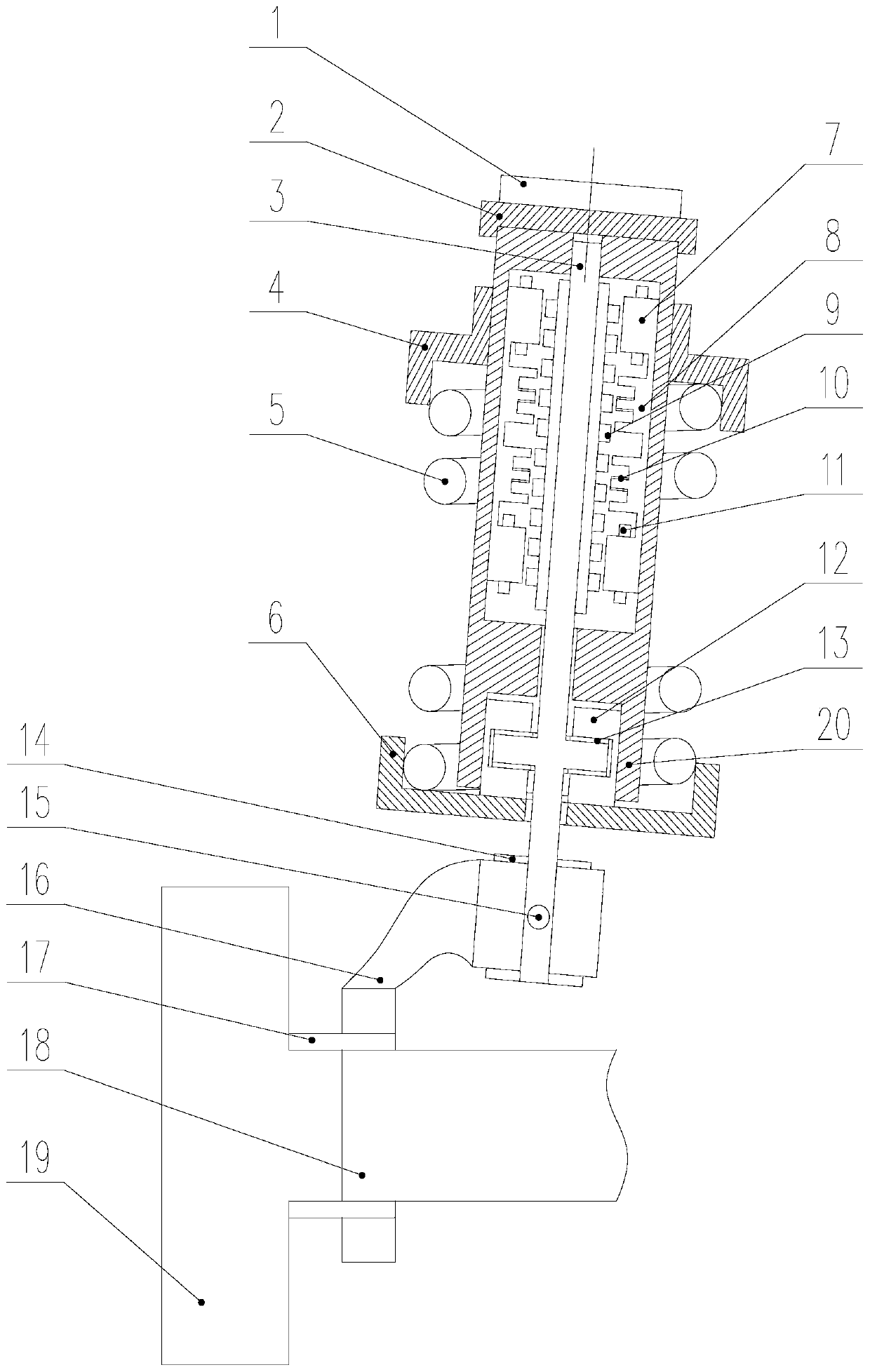
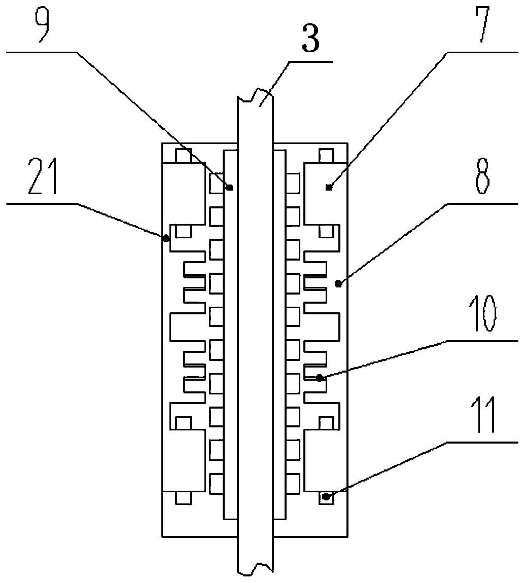
[0020] Such as figure 1 As shown, the present invention includes a connecting plate assembly 1, a motor fixing plate 2, a mechanical shaft 3, a helical spring upper supporting plate 4, a helical spring 5, a helical spring lower supporting plate 6, a rotating stator 7, a linear stator 8, and a motor rotor 9 , linear winding 10, rotating winding 11, connecting plug ring 12, thrust bearing 13, steering bushing 14, connecting pin 15, steering knuckle 16, hub bearing 17, half shaft 18, hub 19 and housing 20.

[0021] Wherein, the connecting plate assembly 1 is located at the uppermost end in the axial direction, and its axial lower end is fixedly connected to the motor fixing plate 2 coaxially. The connecting plate assembly 1 is used to connect the vehicle frame and the suspension structure. The axial lower end of the motor fixing plate 2 is fixedly connected with the axial upper end surface of the casing 20 coaxially.

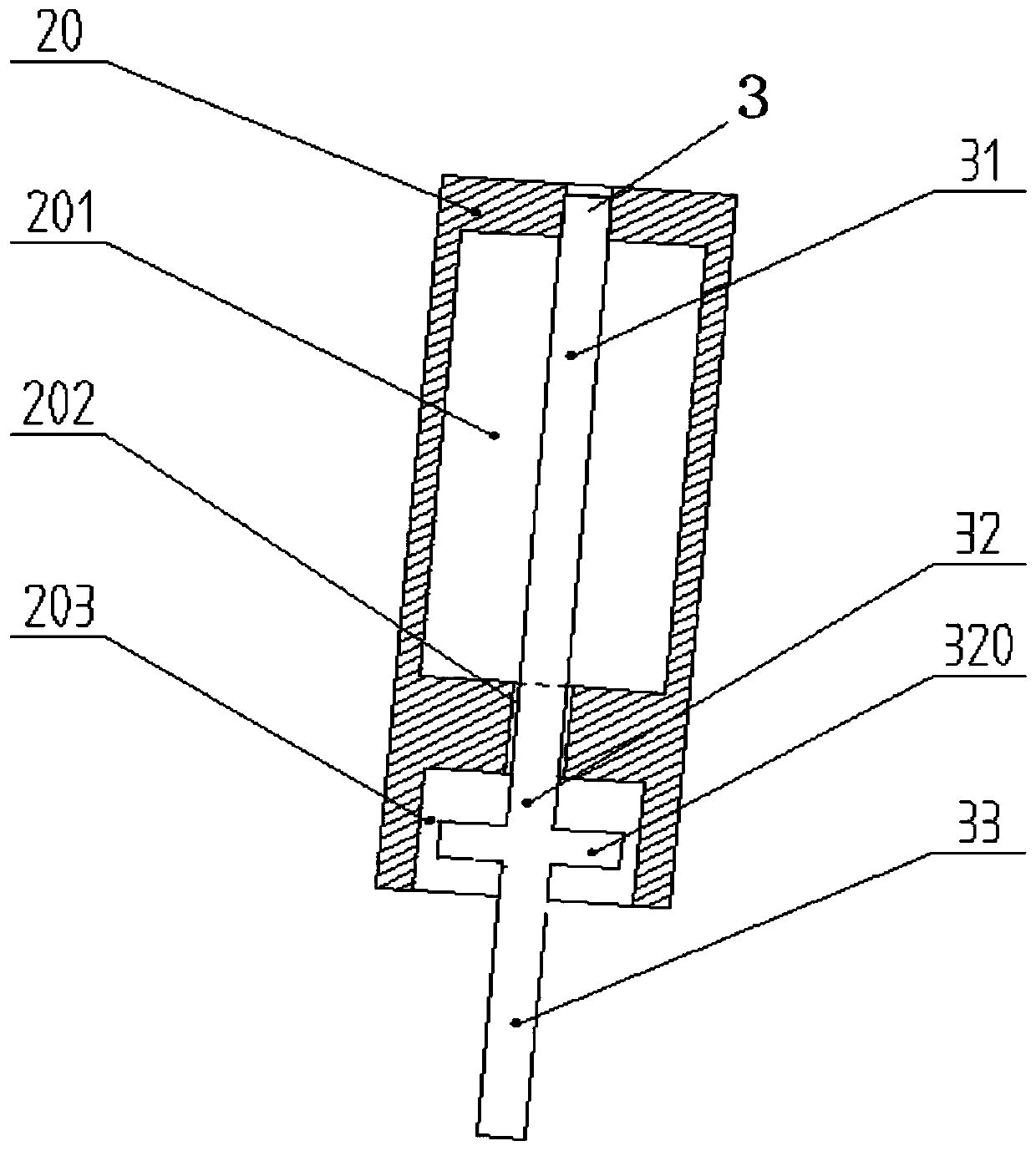
[0022] Such as figure 2 As shown, the casing 20 is a revol...


PUM


Abstract

The invention discloses a steering energy feedback suspension based on a switched reluctance linear rotating motor. A motor cavity, a rotating shaft cavity and a sliding cavity are formed in a shell in an axial direction from top to bottom, the switched reluctance linear rotating motor is arranged in the motor cavity, and a mechanical rotating shaft is sequentially provided with a motor section, asliding section and a steering section from top to bottom in the axial direction. The motor section is coaxially positioned in the motor cavity, the sliding section is positioned in the rotating shaft cavity and the sliding cavity, and the steering section extends out of the shell. A cylindrical thrust disc fixedly sleeves the sliding section, the inner wall of the sliding cavity is in clearancefit connection with the outer wall of a connecting plug ring in a radial direction, and the cylindrical thrust disc sleeves the sliding section and is installed in the connecting plug ring. A spiral spring upper supporting plate and a spiral spring coaxially sleeve the shell, and the lower end of the steering section is connected with a hub through a steering knuckle and a half shaft. According tothe present invention, the suspension system is endowed with a steering function, an original steering system is omitted, the chassis structure of an automobile is simplified, and the structural interference during large-amplitude steering is eliminated.

Description

technical field [0001] The invention relates to vehicle technology, and relates to an energy-feeding suspension structure installed on a vehicle, in particular to an energy-feeding suspension adopting a switched reluctance linear rotary motor. Background technique [0002] The suspension and steering system are important systems in the vehicle. The suspension transmits the force and moment between the tire and the body, which has the function of buffering and shock absorption. The steering system is one of the key systems to maintain the normal driving of the vehicle. Suspension system refers to a connection structure system between the body, frame and wheels, which mainly absorbs the vibration and impact caused by the change of the ground when the car is driving on the road; the function of the steering system is to transfer the force output by the steering gear The sum motion is transmitted to the steering knuckles on both sides of the steering bridge, so that the steering...

Claims


Application Information

Patent Timeline
Patent Type & Authority Applications(China)
IPC IPC(8): B60G13/14B60G15/06B62D5/04
CPCB60G13/14B60G15/068B62D5/0418B60G2200/44B60G2204/1242
Inventor 孙晓东金志佳陈龙周卫琪杨泽斌田翔李可
Owner JIANGSU UNIV
Why Eureka
Try Eureka