Organic luminous display

A light-emitting display, organic technology, applied in the direction of static indicators, instruments, etc., can solve the problem of not reducing the power consumption of the internal power line

Inactive Publication Date: 2007-04-11
AU OPTRONICS CORP
View PDF5 Cites 0 Cited by
  • Summary
  • Abstract
  • Description
  • Claims
  • Application Information

AI Technical Summary

Problems solved by technology

This patent divides the external power line into several sections to reduce the power consumption on the external power line, but does not reduce the power consumption on the internal power line

Method used


Image

  • Organic luminous display
  • Organic luminous display
  • Organic luminous display

Examples


Embodiment Construction

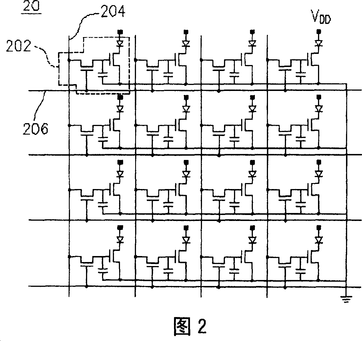
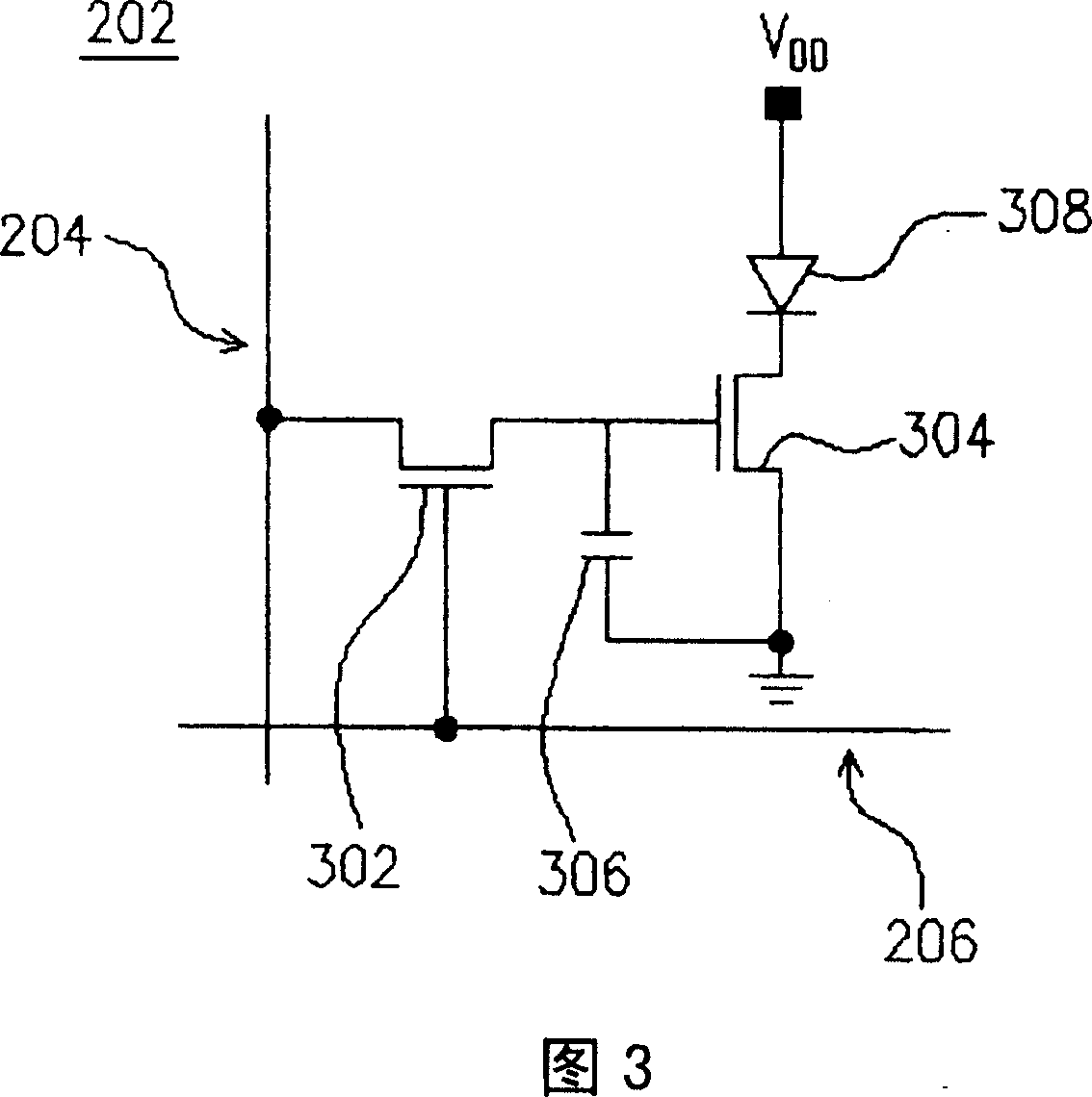
[0032]The organic light emitting display (OLED) of the present invention is an active OLED. Next, please refer to FIG. 2 , which shows the overall structure diagram of the pixel array 20 of the OLED of the present invention. It can be seen from FIG. 2 that the pixel array 20 includes several pixels 202 , several data lines 204 and several scan lines 206 . The present invention uses the effect of current shunting to divide the external power lines into several internal power lines among the pixels, and these internal power lines are separated from each other. Please refer to FIG. 3 for the circuit diagram of the pixel 202 of the OLED of the present invention. It can be seen from FIG. 3 that the pixel 202 includes a switching transistor 302 , a driving transistor 304 , a storage capacitor 306 , and a light emitting element 308 . The switch transistor 302 has a drain, a gate, and a source. The driving transistor 304 has a drain, a gate, and a source. The storage capacitor 306...


PUM


Abstract

The present invention relates to an organic luminous display. It includes several picture elements and an exterior power line. The exterior power line is divided into several interior power lines in the convergence zone of picture element, and these interior power lines can be mutually separated, so that the electric current flowed through these interior power lines can be obviously reduced, therefore the power consumption of electric current on these interior power lines can be reduced. The organic luminous display can save electricity and reduce heat production of panel.

Description

technical field [0001] The present invention relates to an organic light emitting display (Organic Light Emitting Display, referred to as OLED), and in particular to an external power line divided into several internal power lines between several pixels, and these internal power lines will be Active organic light-emitting displays spaced apart from each other. Background technique [0002] The earliest moving images that humans can see are documentary-style movies. Afterwards, the invention of the cathode ray tube (Cathode Ray Tube, referred to as CRT) successfully derived commercial TV sets and became a must-have household appliance for every family. With the development of science and technology, the application of CRT has expanded to desktop monitors in the computer industry, making CRT popular for nearly decades. However, all types of displays made of CRTs face the problem of radiation, and because of the structure of the internal electron gun, the display is bulky and...

Claims


Application Information

Patent Timeline
Patent Type & Authority Patents(China)
IPC IPC(8): G09G3/32G09G3/30G09G3/3208
Inventor 宋志峯
Owner AU OPTRONICS CORP
Why Eureka
Try Eureka