Chip washing equipment preventing blocking of pipe wall

A chip and tube wall technology, which is applied in the field of chip cleaning equipment with the function of preventing tube wall clogging, can solve the problems of clogging pipelines, waste of time, particles adhering to the tube wall, etc., to avoid clogging and prevent tube wall clogging. Effect

Inactive Publication Date: 2007-04-11
WINBOND ELECTRONICS CORP
View PDF3 Cites 1 Cited by
  • Summary
  • Abstract
  • Description
  • Claims
  • Application Information

AI Technical Summary

Problems solved by technology

Therefore, when the dry nitrogen gas is passed into the cleaning solution, especially an aqueous solution such as a high-concentration saturated buffer oxide layer etching solution (Buffer HF, referred to as BHF or Buffer OxideEtcher, referred to as BOE), a large amount of water absorption will occur, resulting in adhesion on The moisture in the solution on the pipe wall at the outlet of the pipeline 14 will precipitate out solute due to drying, which will cause particles to adhere to the pipe wa...

Method used


Image

  • Chip washing equipment preventing blocking of pipe wall
  • Chip washing equipment preventing blocking of pipe wall
  • Chip washing equipment preventing blocking of pipe wall

Examples


Embodiment Construction

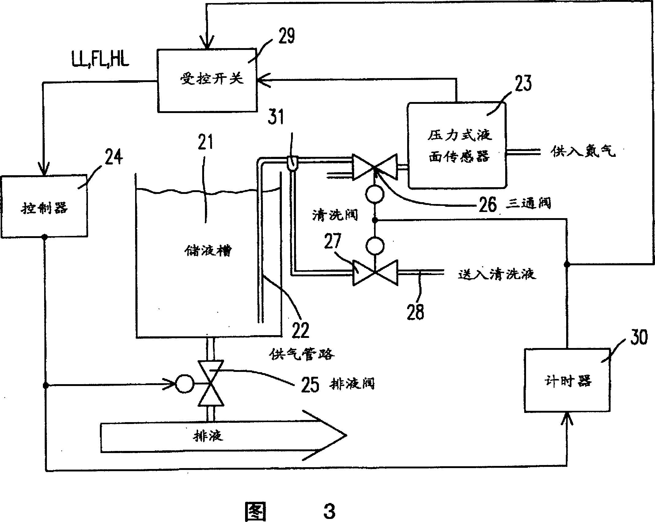
[0023] Please refer to FIG. 3 , which is a schematic structural diagram of a chip cleaning device according to a preferred embodiment of the present invention. As shown in the figure, it includes a cleaning solution storage device composed of a liquid storage tank 21, a controller 24 and a liquid discharge valve 25, a gas supply pipeline 22 for the liquid discharge valve, a pressure type liquid level sensor 23 and an automatic cleaning device. The cleaning solution required for cleaning the chip is stored in the liquid storage tank 21 , such as buffer oxide etchant (Buffer HF, BHF for short or Buffer Oxide Etcher, BOE for short). The gas supply pipeline 22 passes an inert gas into the buffered oxide layer etchant stored in the liquid storage tank 21, wherein the air pressure in the gas supply pipeline 22 is washed with the liquid storage tank 21. The liquid level of the cleaning solution changes, so it can cooperate with the pressure type liquid level sensor 23 to detect the l...


PUM


Abstract

An equipment for washing chips features its additional cleaner for pipeline. Under the trigger of liquid drainage action, the gas supply into the gas pipeline is stopped, but a cleaning liquid that dissolves the particles in the gas pipeline is introduced into it to clean the inner surface of the pipeline. After cleaning is finished, the cleaning liuqid is cut off and gas is supplied into the gas pipeline again.

Description

technical field [0001] The invention relates to a chip cleaning device, in particular to a chip cleaning device with the function of preventing tube wall from being clogged. Background technique [0002] In today's semiconductor manufacturing process, chip cleaning equipment is a frequently used and indispensable device. Please refer to Fig. 1, which is a schematic structural diagram of commonly used chip cleaning equipment, wherein the liquid storage tank 11 is used to store cleaning solutions, such as buffer oxide layer etchant (Buffer HF, referred to as BHF or Buffer OxideEtcher, referred to as BOE ), and in order to enable the controller 12 of the chip cleaning equipment to effectively grasp the liquid level height of the cleaning solution in the liquid storage tank 11, a pressure-type liquid level sensor 13 (Pressure Leveling Sensor) is provided, which uses an inert gas (Usually nitrogen) passes through the pressure type liquid level sensor 13 and then uses a pipeline ...

Claims


Application Information

Patent Timeline
IPC IPC(8): H01L21/304B08B3/04
Inventor 施本成
Owner WINBOND ELECTRONICS CORP
Why Eureka
Try Eureka