Adjustable extemal cavity laser

A technology of laser cavity and laser equipment, used in lasers, laser parts, semiconductor lasers, etc., can solve the problems of tunable external cavity laser size, cost, complexity and sensitivity increase

Inactive Publication Date: 2007-05-16
INTEL CORP
View PDF9 Cites 6 Cited by
  • Summary
  • Abstract
  • Description
  • Claims
  • Application Information

AI Technical Summary

Problems solved by technology

[0004] Achieving these goals often results in increased size, cost, complexity, and sensitivity of tunable external cavity lasers

Method used


Image

  • Adjustable extemal cavity laser
  • Adjustable extemal cavity laser
  • Adjustable extemal cavity laser

Examples


Embodiment Construction

[0040] Reference is made more particularly to the drawings for the purpose of illustrating the invention embodied in the apparatus shown in FIGS. 1 to 17 . It should be understood that the device may vary in configuration and detail of components, and the method may vary in detail and order of actions without departing from the basic concept disclosed. The invention is primarily disclosed in terms of the use of external cavity lasers. However, the invention can be used with various types of laser devices and optical systems. It is to be understood that the terminology used herein is for the purpose of describing particular embodiments only and is not limiting, since the scope of the present invention is defined only by the claims. The relative sizes of components, as well as the distances between them, shown in the figures are of many examples exaggerated for clarity and therefore should not be considered limiting.

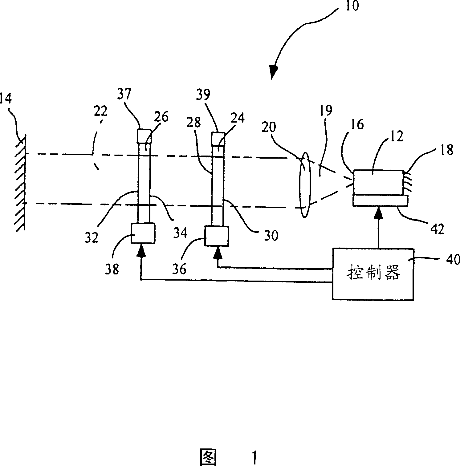
[0041] Referring to Figure 1, there is shown a laser devic...


PUM


Abstract

Apparatus and methods that utilize dual, tunable elements to provide for selective wavelength tuning of a light beam. The apparatus comprises a first tunable wavelength selection element (24) positioned in a light beam and having a first adjustable free spectral range, a second tunable wavelength selection element (26) positioned in the light beam and having a second adjustable free spectral range, with the first and second tunable wavelength selection elements configured to define a joint transmission peak that is adjustable in phase according to tuning of the first and second tunable wavelength selection elements.

Description

technical field [0001] The need for increased bandwidth in fiber optic communications is driving the development of advanced laser transmitters that can be used in Dense Wavelength Division Multiplexing (DWDM) systems where multiple separate data streams are propagated in a single fiber. Each data stream is produced by the modulated output of a semiconductor laser at a specific channel frequency or wavelength, and multiple modulated outputs are combined into a single fiber. The International Telecommunication Union (ITU) currently proposes a channel spacing requirement of approximately 0.4 nanometers, or about 50 GHz, to allow up to 128 channels to be carried by a single fiber within the bandwidth of currently available fibers and fiber amplifiers. In the future, greater bandwidth requirements will Most likely resulting in less channel isolation. Background technique [0002] Telecom DWDM systems are mainly based on distributed feedback (DFB) lasers. DFB lasers are stabili...

Claims


Application Information

Patent Timeline
Patent Type & Authority Patents(China)
IPC IPC(8): H01S3/10H01S3/08H01S5/14
CPCH01S5/141
Inventor M·E·麦唐纳A·J·戴伯W·B·查普曼N·马卢夫
Owner INTEL CORP
Why Eureka
Try Eureka