
Miniature circuit breaker pole

A technology for small circuit breakers and circuit breakers, which is applied to circuit breaker components, circuit breaker contacts, circuits, etc., can solve the problem of reducing disconnection capacity, achieve the effect of improving functional characteristics and optimizing space requirements

Inactive Publication Date: 2007-06-06
ABB (SCHWEIZ) AG
View PDF1 Cites 2 Cited by
  • Summary
  • Abstract
  • Description
  • Claims
  • Application Information

AI Technical Summary

Problems solved by technology

[0006] At present, in known types of miniature circuit breakers, on the one hand such solution in which the breaking capacity is increased by increasing the size of the components used and by adopting a specially constructed structure, thus increasing the width of the circuit breaker relative to the width of the standard basic module, and on the other hand , keep this standard width, but buy a circuit breaker with reduced breaking capacity

Method used


Image

  • Miniature circuit breaker pole
  • Miniature circuit breaker pole
  • Miniature circuit breaker pole

Examples


Embodiment Construction

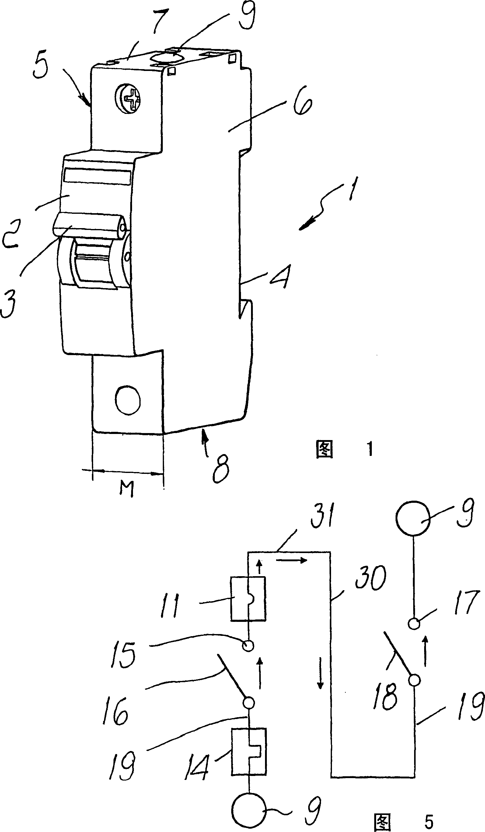
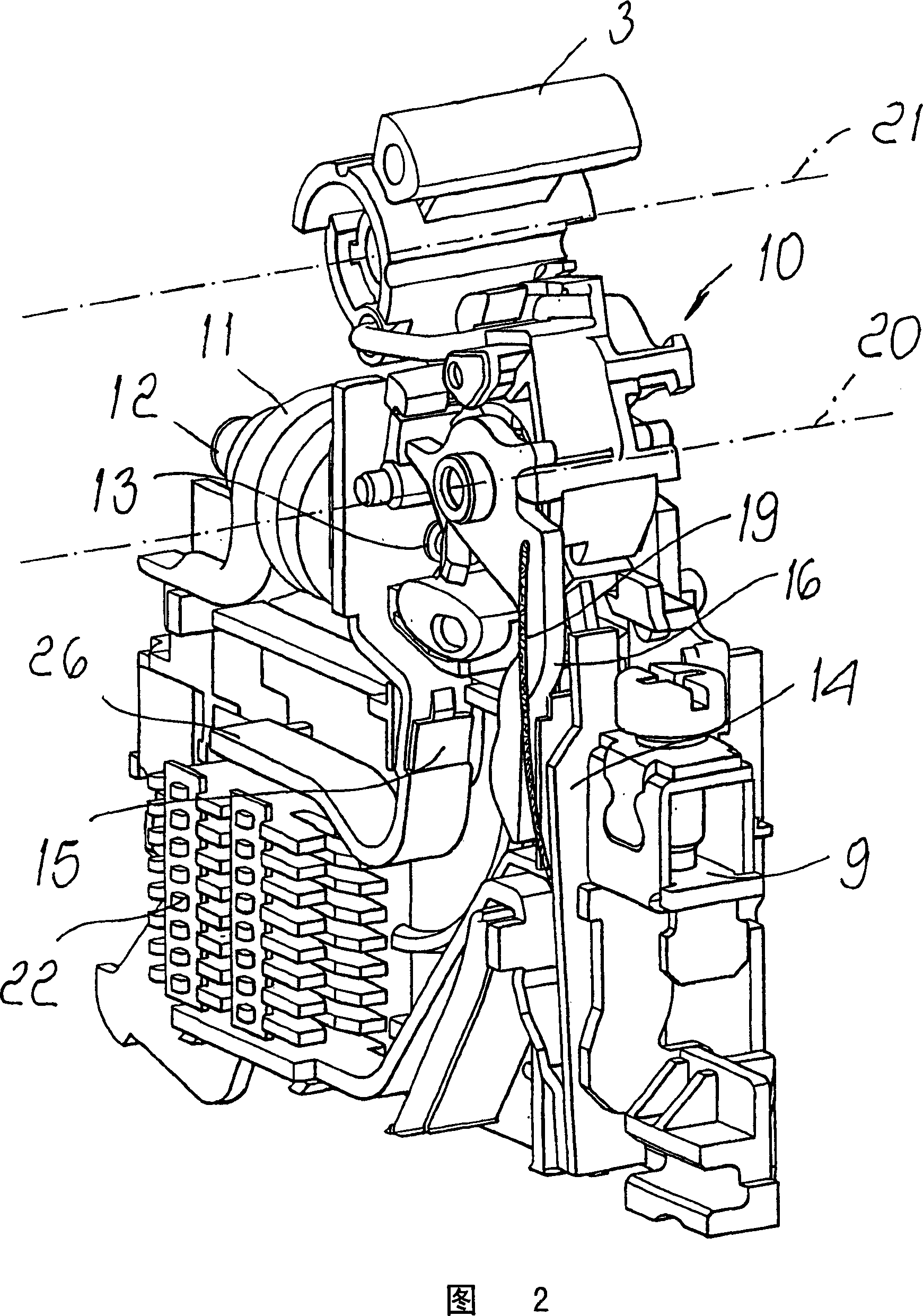
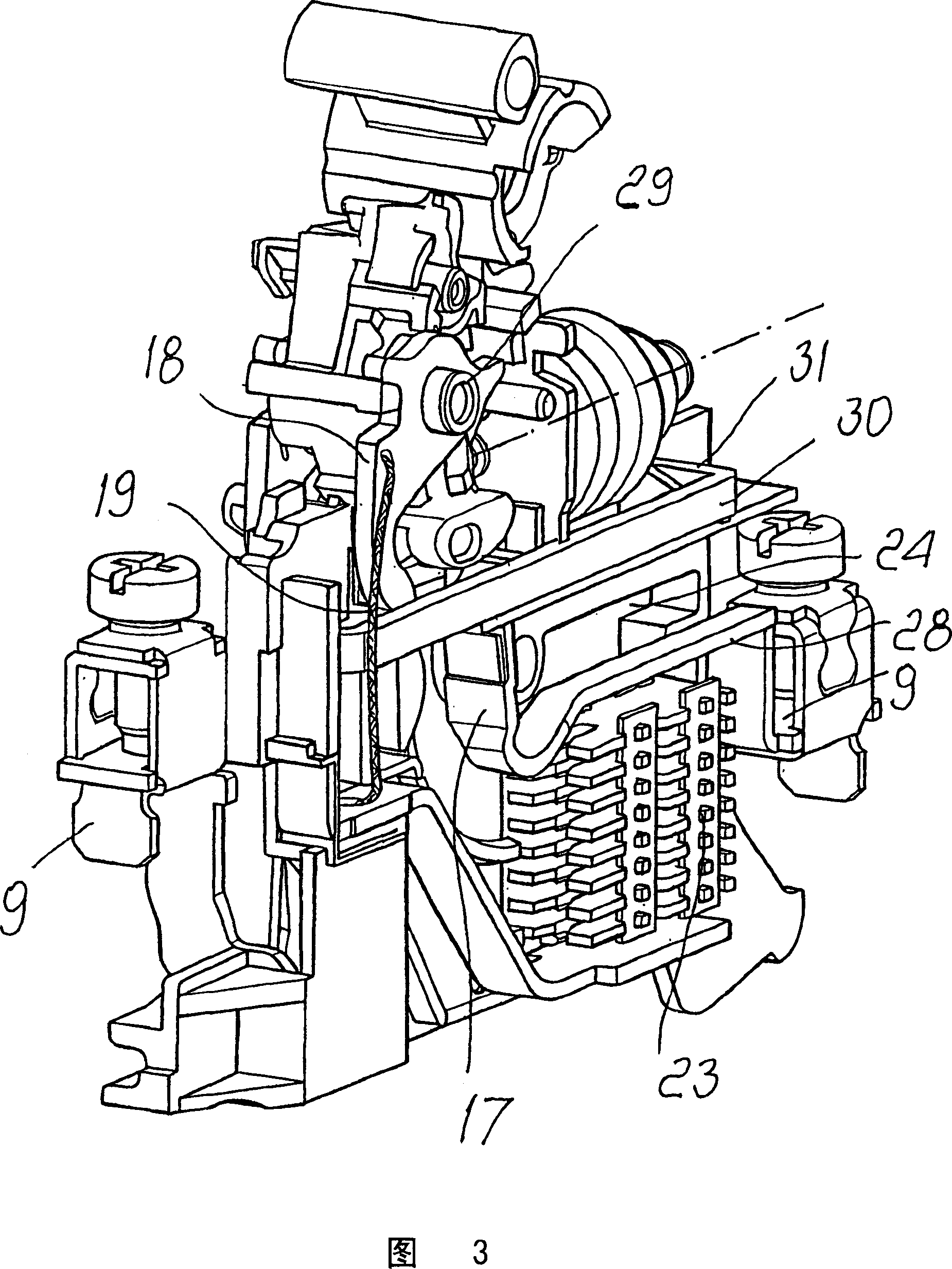
[0022] With reference to the cited figures, the miniature circuit breaker bar according to the invention comprises a housing 1 having a front wall 2 from which an actuating handle 3 protrudes, which handle is coupled to the housing so that it can be rotated around Pivot with suitably arranged; Rear wall 4, this rear wall is shaped conveniently so that connect unillustrated supporting guide, for example DIN track; Two side walls 5 and 6, these side walls are substantially parallel to each other, and Their distance is equal to the basic module M, which defines the width of the circuit breaker; upper wall 7 and lower wall 8 . Moreover, there are two corresponding terminals 9 on the housing, one of which is only partially visible in Figure 1, and corresponding clamping terminals for connection to the pole to be protected in the form of input and output of the circuit breaker. The phase; terminals 9 of the low voltage circuit may be arranged at the upper and lower walls, as shown i...


PUM


Abstract

A single-pole miniature circuit breaker, comprising:-- a casing on which there are two terminals for connection, in input and in output from the circuit breaker, to a phase of a low-voltage electric circuit, said casing having a front wall from which an actuation lever protrudes, a rear wall for coupling to a supporting element, two side walls that are substantially mutually parallel and whose distance is equal to a base module M, an upper wall and a lower wall, inside the casing there being provided:--fixed and moving contact means that can be mutually separated in order to interrupt the flow of current in said phase;-- a kinematic mechanism that is operatively connected to said actuation lever and is suitable to move said moving contact means;--electric are quenching means;--a device for protection against short-circuits, which comprises a coil and a moving striker suitable to interact operatively with said kinematic mechanism;-- a device for protection against overloads, which comprises a heat-sensitive element that is suitable to interact operatively with the kinematic mechanism; characterized in that said fixed and moving contact means comprise a first pair of contacts, having a first fixed contact and a first moving contact, and a second pair of contacts, having a second fixed contact and a second moving contact, a first arc quenching chamber and a second arc quenching chamber being respectively associated with said first and second pairs of contacts, said first and second pairs of contacts being electrically series-connected to each other and being crossed by currents that have the same direction.

Description

technical field [0001] The present invention relates to a miniature circuit breaker pole for low voltage applications, ie operating voltages up to 1000 volts. Background technique [0002] It is known that low voltage electrical systems use suitable protective devices, generally referred to in the art as modular circuit breakers or miniature circuit breakers. [0003] These circuit breakers are dimensionally characterized in that, depending on the number of poles used, the width of these circuit breakers is equal to the width of a standard module or is a multiple of the width of a standard module, as stated in the relevant international standards, and these circuit breakers pass through It is normally used mounted on a suitable support element, such as a DIN rail, which in turn is usually placed in a suitably arranged electrical enclosure. [0004] One of the main requirements for a modular circuit breaker of the residual current or magnetothermal type is the ability to ens...

Claims


Application Information

Patent Timeline
IPC IPC(8): H01H73/18H01H9/40H01H73/04
CPCH01H73/18H01H9/40H01H73/04
Inventor A·安托尼尔兹F·林科
Owner ABB (SCHWEIZ) AG
Learn More