
Cylindrical lens component and producing method, rear projection screen and rear-projection television

A cylindrical mirror and component technology, applied in the optical field, can solve the problems of black stripes and manufacturing difficulties, and achieve the effect of fine stripes, high resolution, and high contrast

Inactive Publication Date: 2007-06-13
张益民 +1
View PDF5 Cites 0 Cited by
  • Summary
  • Abstract
  • Description
  • Claims
  • Application Information

AI Technical Summary

Problems solved by technology

[0003] With the increasing popularity of high-definition projection TVs using LCD, DLP, and LCOS as projection sources, there is a great demand for the screens used in such projection TVs. Now the pixels of high-definition projection TVs have grown from tens of thousands of pixels in the past to The current several million pixels require the pitch of the cylindrical mirror to be finer (at least less than 0.25mm) to eliminate the moiré fringes caused by the cylindrical mirror period and the pixel period; but it was used in the three-tube CRT rear projection TV in the past The pitch of the cylindrical mirror components in the screen used is generally greater than 0.5mm, which cannot meet the requirements of the current high-definition projection TV. It is very difficult to manufacture a smaller pitch, because the traditional cylindrical mirror mentioned above The incident light of the mirror component is focused near the center of the cylindrical convex lens on the exit surface through the cylindrical convex lens on the incident surface, so the smaller the pitch, the thinner the cylindrical lens component will be, and the higher the relative position accuracy requirements for the front and rear convex lenses. , otherwise the outgoing light will hit the black stripes

Method used


Image

  • Cylindrical lens component and producing method, rear projection screen and rear-projection television
  • Cylindrical lens component and producing method, rear projection screen and rear-projection television
  • Cylindrical lens component and producing method, rear projection screen and rear-projection television

Examples


Embodiment 1

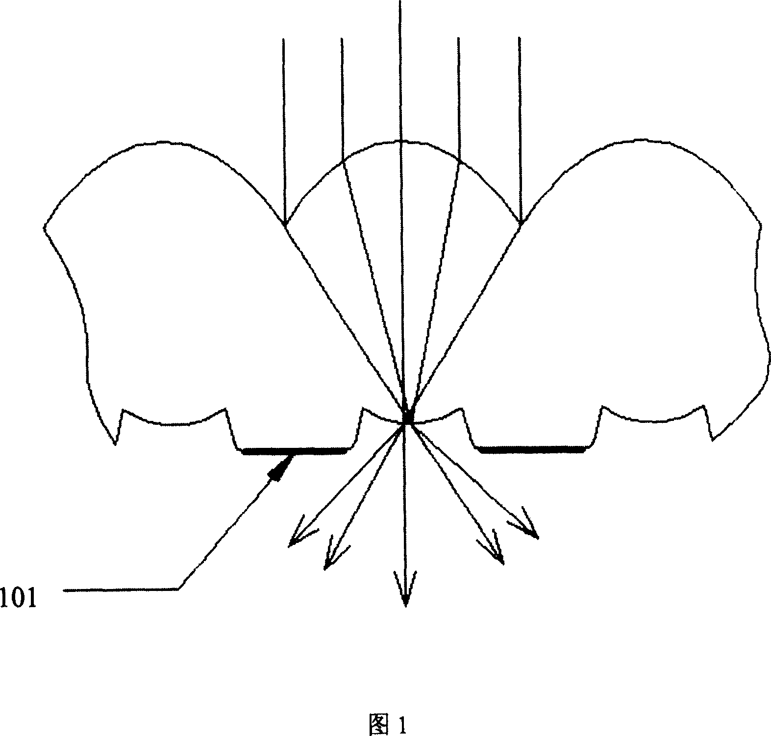
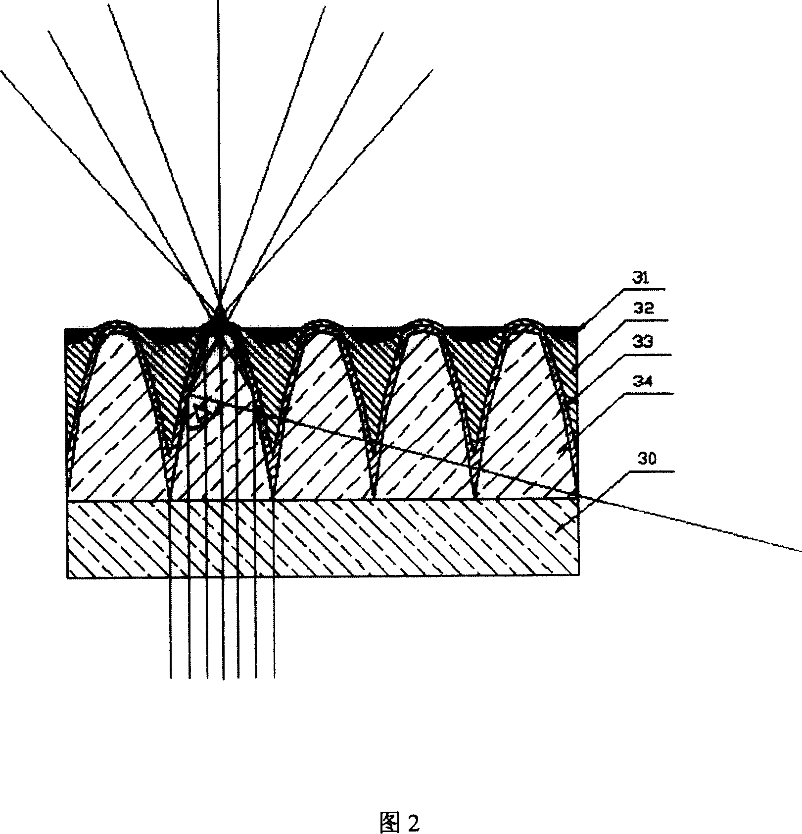
[0050] Referring to FIG. 2 , the surface of the cylindrical mirror array 34 is covered with a transparent material 33 , and the refractive index of the transparent material 33 is smaller than that of the cylindrical mirror material. A coating material 32 is filled between two adjacent cylindrical mirrors, and the light-absorbing stripes 31 are black stripes, and the black stripes are located between two adjacent cylindrical mirrors and on the coating material 32. The distance between two adjacent black stripes is not more than 0.25mm. The coating material 32 is photocurable glue or conductive material.

[0051] A transparent sheet (30) is also glued under the cylindrical lens array 34. As the unit of the cylindrical mirror array, the shape of the cylindrical mirror satisfies the following relationship:

[0052] Assuming that the final projected light energy has a spatial distribution function of f(θ), the projected light energy passes through the cylindrical mirror

[0053]...

Embodiment 2

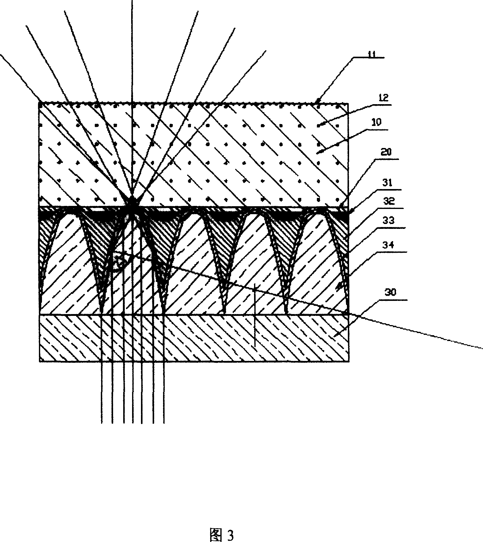
[0062] Referring to FIG. 4 , the difference between this embodiment and Embodiment 1 is that a scattering layer 10 is bonded above the cylindrical lens array 34 and the black stripes 31 , and the scattering layer 10 contains organic scattering particles 12 .

Embodiment 3

[0064] The difference between this embodiment and Embodiment 1 is that organic scattering particles 12 are distributed in the transparent material 33 . There is also a dielectric layer on the cylindrical lens array 34, and the surface of the dielectric layer is a fine matte surface. A low-reflection dielectric film can also be coated on the surface of the dielectric layer 10 .


PUM


Abstract

The present invention relates to optical technology, and is especially cylindrical lens constituent for rear projection screen and its making process. The cylindrical lens combination includes cylindrical lens array and light absorbing stripes and features that the surface of the cylindrical lens combination is covered with transparent material of refractive index smaller than that of the cylindrical lens material. The present invention has the benefit effect that light is reflected totally in the sides of the cylindrical lens units and outgone from the top of cylindrical lens units so as to form black stripes in the non-outgoing areas, resulting in high contrast. The present invention provides cylindrical lens combination with high resolution and high contrast for high resolution rear projecting TV.

Description

technical field [0001] The invention relates to optical technology, in particular to a cylindrical lens component used in a rear projection screen and a manufacturing method. Background technique [0002] The rear projection screen is usually composed of a Fresnel lens and a cylindrical lens component. The general structure of the cylindrical lens component in the screen used in the three-tube CRT rear projection TV is shown in Figure 1. The incident light passes through the incident surface. The lenticular convex lens is focused near the center of the lenticular convex lens on the exit surface, and a convex part is formed in the middle area of ​​the adjacent lenticular convex lens on the exit surface, and black stripes are printed on the convex part, which can ensure the largest area of ​​blacking on the exit surface side , thereby increasing the contrast as much as possible. [0003] With the increasing popularity of high-definition projection TVs using LCD, DLP, and LCOS...

Claims


Application Information

Patent Timeline
Patent Type & Authority Patents(China)
IPC IPC(8): G02B3/06G03B21/62H04N5/74H04N9/31G03B21/625
Inventor 张益民霍永峰
Owner 张益民
Learn More