Perceptive bionic manipulator for clinical injured finger rehabilitation
A manipulator and finger technology, applied in the field of perceptual bionic manipulator and its combined modules, can solve the problem that force position information and rehabilitation effect cannot be established effectively, the scope of application is small, and there is no precise control of joint position, joint speed and rehabilitation force. And other issues
- Summary
- Abstract
- Description
- Claims
- Application Information
AI Technical Summary
Problems solved by technology
Method used
Image
Examples
specific Embodiment approach 1
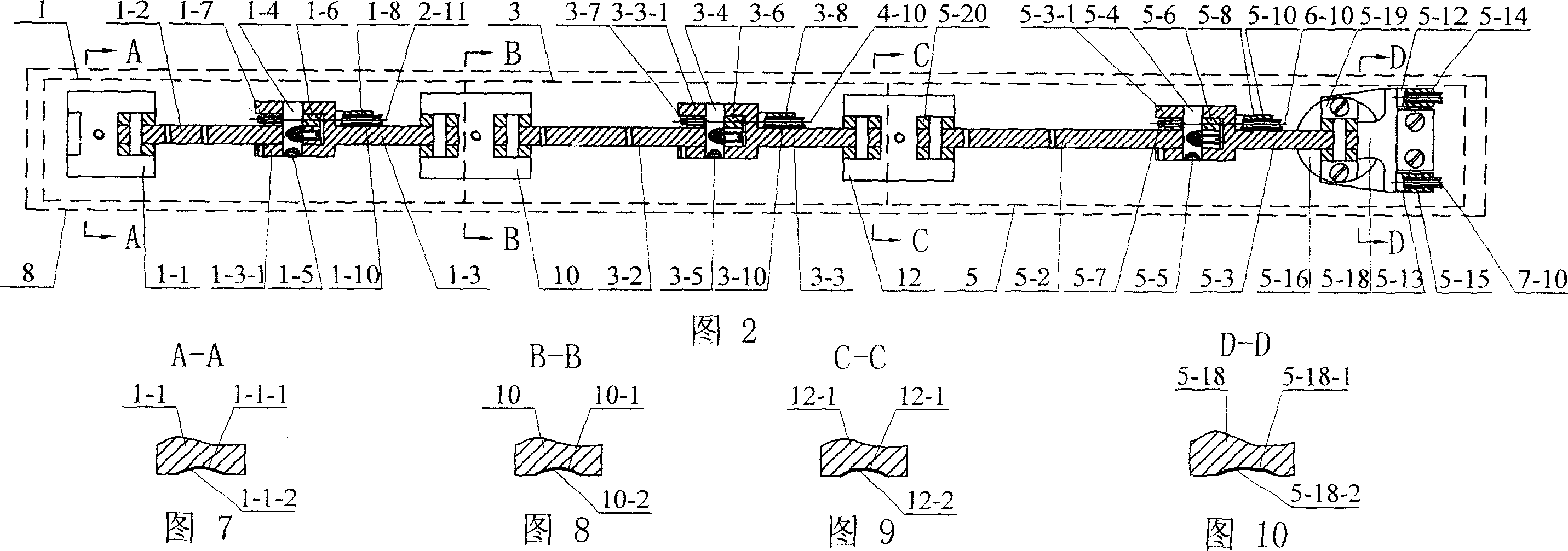
[0006] Specific embodiment one: this embodiment is described in conjunction with Fig. 1, Fig. 2, Fig. 3, Fig. 4, and this embodiment is made up of the 3rd knuckle module 1, frame assembly 11 and nail bionic muscle module 2; The 3rd knuckle module 1 consists of a third base 1-1, a third torque sensor 1-2, a third connecting rod 1-3, a third shaft 1-4, a third magnetic steel 1-5, a third pulley 1-6, a third Fixed column 1-7, first cylinder 1-8, second cylinder 1-9, first spring 1-10, second spring 1-11, second base 10; third base 1-1 Hinged with the left end of the third torque sensor 1-2, the third torque sensor 1-2 and the third pulley 1-6 are contained in the fork 1-3-1 of the third connecting rod 1-3 and use the third shaft 1- 4 is connected with the third connecting rod 1-3, the end surface of the third pulley 1-6 is fixedly equipped with a third fixed column 1-7, and the front end shaft hole of the third shaft 1-4 is equipped with a third magnetic steel 1- 5. The third co...
specific Embodiment approach 2
[0007] Specific embodiment two: illustrate this embodiment in conjunction with Fig. 3, nail tensioning mechanism 2-2 among the present embodiment is made up of first guide support 2-2-1, first fastening connector 2-2-2, first guide pin 2-2-3, the first fixed pin 2-2-4 is composed; the left end of the first guide bearing 2-2-1 passes through the first fastening connector 2-2-2 and the left end upper bracket 11- in the frame assembly 11 1 is connected, the upper end hole of the first guide bearing 2-2-1 is equipped with the lower end of the first fixed pin 2-2-4, and the upper end of the first fixed pin 2-2-4 is connected with the upper cover plate 11 in the frame assembly 11 The lower end faces of -5 are in contact, the upper end of the first guide pin 2-2-3 is installed in the lower end hole of the first guide support 2-2-1, and the lower end of the first guide pin 2-2-3 is installed in the frame assembly 11 In the first long hole 11-6-1 of the mounting plate 11-6. Other comp...
specific Embodiment approach 3
[0008]Specific embodiment three: this embodiment is described in conjunction with Fig. 1, Fig. 2, Fig. 4, Fig. 5, and this embodiment is made up of second knuckle module 3, frame assembly 11 and second bionic muscle module 4; The second knuckle module 3 consists of the second base 10, the second torque sensor 3-2, the second connecting rod 3-3, the second shaft 3-4, the second magnetic steel 3-5, the second pulley 3-6, and the second fixed column 3-7, the third cylinder 3-8, the fourth cylinder 3-9, the third spring 3-10, the fourth spring 3-11 and the first support 12; the second support 10 and the second torque The left end of sensor 3-2 is hinged, and the second torque sensor 3-2 and the second pulley 3-6 are contained in the fork 3-3-1 of the second connecting rod 3-3 and use the second shaft 3-4 and the second The connecting rod 3-3 is connected, the end face of the second pulley 3-6 is fixedly equipped with a second fixed column 3-7, and the second magnetic steel 3-5 is ...
PUM
 Abstract
Description
Claims
Application Information
 - R&D
- Intellectual Property
- Life Sciences
- Materials
- Tech Scout
- Unparalleled Data Quality
- Higher Quality Content
- 60% Fewer Hallucinations
Browse by: Latest US Patents, China's latest patents, Technical Efficacy Thesaurus, Application Domain, Technology Topic, Popular Technical Reports.
© 2025 PatSnap. All rights reserved.Legal|Privacy policy|Modern Slavery Act Transparency Statement|Sitemap|About US| Contact US: help@patsnap.com


