
Oscillator circuit

A technology of oscillating circuit and ring oscillator, which is applied in the direction of electric pulse generator circuit, logic circuit to generate pulse, electrical components, etc., can solve the problems of decreased driving ability, inability to rise, and increased impedance, so as to prevent abnormal oscillation or stop oscillation Effect

Inactive Publication Date: 2007-07-18
SANYO ELECTRIC CO LTD
View PDF4 Cites 0 Cited by
  • Summary
  • Abstract
  • Description
  • Claims
  • Application Information

AI Technical Summary

Problems solved by technology

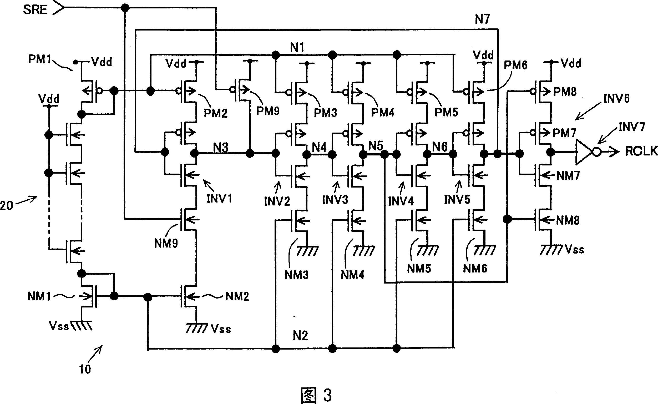
If the potential of the node N1 rises slightly, the impedance of the P-channel MOS transistors PM2 to PM6 increases, and the driving capability decreases compared with the N-channel MOS transistors NM2 to NM6
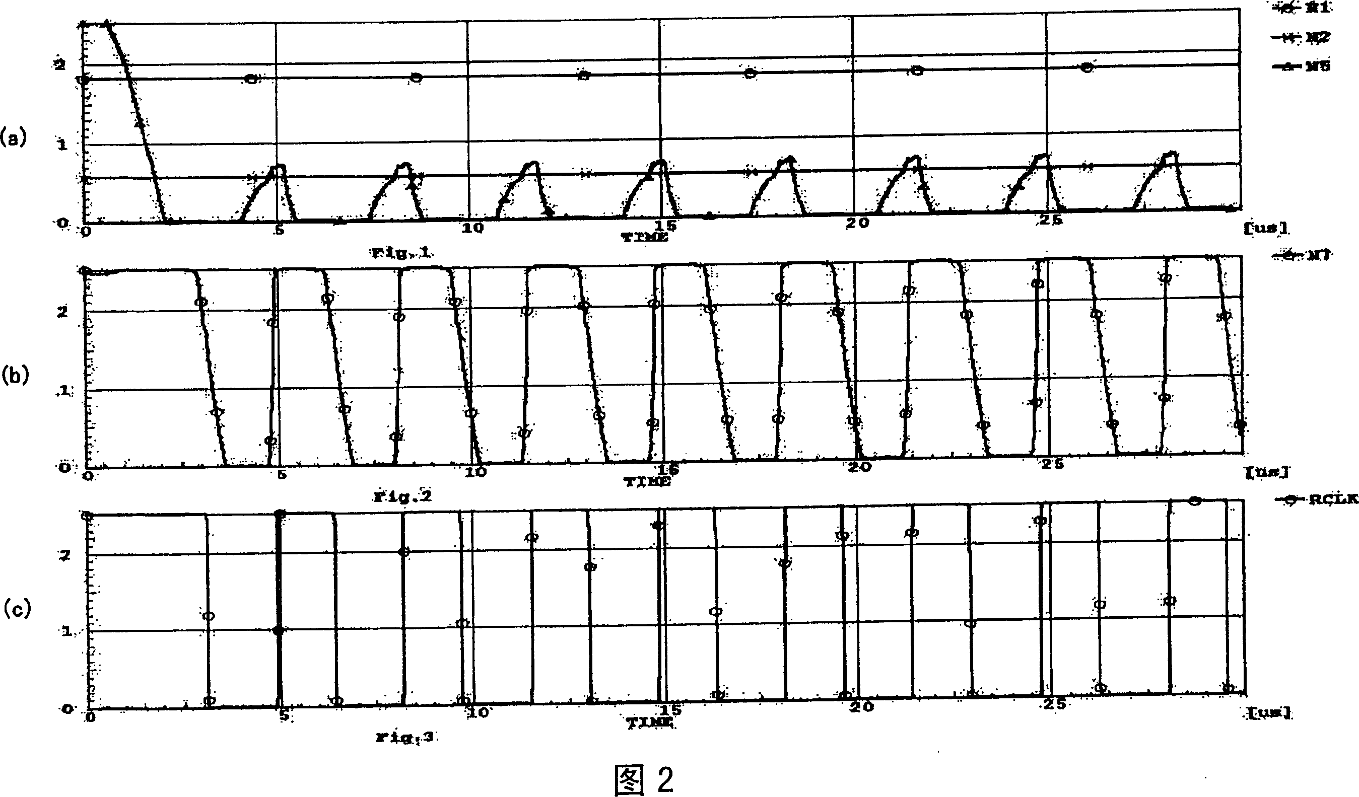
Then, as shown in FIG. 5(a), the high level of the node N5, which is the output of the inverter INV3, cannot rise to the power supply potential Vdd.

Method used


Image

  • Oscillator circuit
  • Oscillator circuit
  • Oscillator circuit

Examples


Embodiment Construction

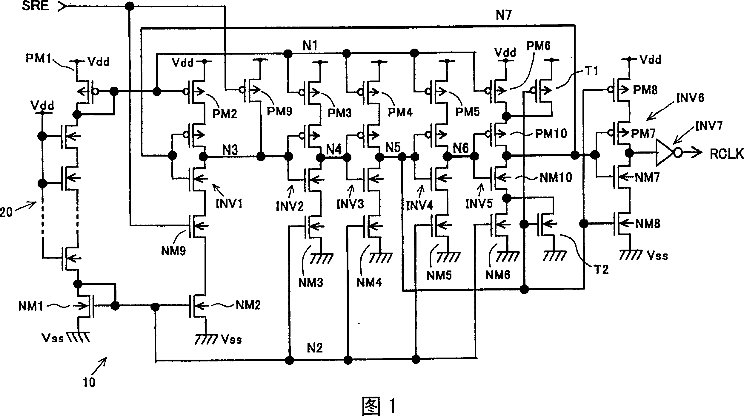
[0026] Next, an oscillation circuit according to an embodiment of the present invention will be described with reference to the drawings. FIG. 1 is a circuit diagram of the oscillation circuit. The oscillating circuit is equipped with: an auxiliary transistor T1, which is used to assist the output of the CMOS inverter INV5 of the final stage to oscillate to the maximum according to the output of the CMOS inverter INV3 before the second stage through the final stage CMOS inverter INV5 to the power supply potential Vdd; and an auxiliary transistor T2, which is used to assist the maximum oscillation to the ground potential Vss. Other circuit structures are the same as those in Figure 3.

[0027] The first auxiliary transistor T1 is composed of a P-channel MOS transistor. The power supply potential Vdd is applied to its source, and the output of the CMOS inverter INV3 is applied to its gate. The source of the P-channel type MOS transistor PM10 is connected to the output of the d...


PUM


Abstract

The invention aims to prevent a ring oscillation from an abnormal oscillation and an oscillation interruption in a ring oscillator type oscillation circuit provided with a current mirror current limiting circuit. The ring oscillator includes CMOS inverters INV1 to INV5 each connected serially in which an output of the CMOS inverter INV5 of the last stage is connected to an input of the CMOS inverter INV1 of the first stage to be fed back. The current mirror current limiting circuit for limiting the current to be flowed through the CMOS inverters INV1 to INV5 is also provided. An auxiliary transistor T1 for assisting the output of the CMOS inverter INV5 to make full swing up to a power source potential Vdd, and an auxiliary transistor T2 for assisting full swing up to a ground potential Vss.

Description

technical field [0001] The present invention relates to a ring oscillator (ringoscillator) type oscillation circuit provided with a current mirror-current limiting circuit. Background technique [0002] Conventionally, ring oscillators have been used as oscillation circuits for various semiconductor integrated circuits. When used as an oscillation circuit for self-refresh in a memory such as a DRAM, it is necessary to obtain a low-frequency oscillation clock signal. Therefore, low-frequency oscillation is realized by suppressing the current of the ring oscillator by the current mirror-current limiting circuit. [0003] FIG. 3 is a circuit diagram showing a ring oscillator type oscillation circuit provided with a current mirror-current limiting circuit studied by the present inventors. The oscillating circuit is vertically connected with CMOS inverters INV1, INV2, INV3, INV4, and INV5, and the output of the final CMOS inverter INV5 is fed back to the output of the primary C...

Claims


Application Information

Patent Timeline
Patent Type & Authority Patents(China)
IPC IPC(8): H03K3/354H03K3/011H03K3/03
CPCH03K3/011H03K3/0315H03K3/354
Inventor 后藤贤介
Owner SANYO ELECTRIC CO LTD
Learn More