
Laser device

A technology of laser device and light source, which is applied to lasers, laser parts, phonon exciters, etc., can solve the problems of light source damage and reflected light not being separated, and achieve the effect of preventing abnormal oscillation

Inactive Publication Date: 2012-12-12
FUJIKURA LTD
View PDF4 Cites 3 Cited by
  • Summary
  • Abstract
  • Description
  • Claims
  • Application Information

AI Technical Summary

Problems solved by technology

[0005] However, the laser device described in the above-mentioned Patent Document 1 is only used to grasp the state of the workpiece and the state of the laser guidance by monitoring the light input as reflected light.
In addition, in such a laser device, part of the reflected light may propagate toward the light source or the like without being separated.
In this case, if there is an amplifier in the light source, abnormal oscillation may occur in the amplifier, and there is a possibility that the light source may be damaged by the strong light generated by the abnormal oscillation.

Method used


Image

  • Laser device
  • Laser device
  • Laser device

Examples


no. 1 Embodiment approach

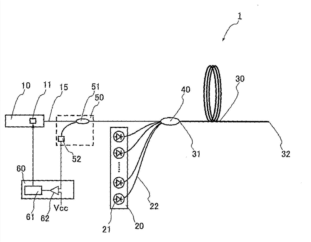
[0023] figure 1 It is a figure which shows the laser apparatus of 1st Embodiment of this invention.

[0024] Such as figure 1 As shown, the laser device 1 is a fiber laser device, which mainly includes a seed light source 10 as a light source for outputting seed light as amplified light, an excitation light source 20 as an excitation part for outputting excitation light, and inputting seed light and excitation light. Amplifying optical fiber 30 as an amplifier, combiner 40 connecting seed light source 10 and excitation light source 20 to amplifying optical fiber 30 , monitoring unit 50 arranged between seed light source 10 and amplifying optical fiber 30 , control unit for controlling seed light source 10 60. Such a laser device 1 is a so-called MO-PA type laser device in which the seed light source 10 is an MO (Master Oscillator) and the excitation light source 20 and amplifying fiber 30 are a PA (Power Amplifier).

[0025] The seed light source 10 has, for example, a seed...

no. 2 Embodiment approach

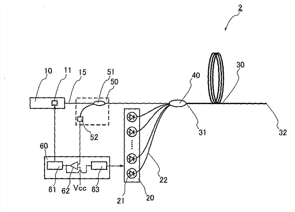
[0046] Next, refer to image 3 A second embodiment of the present invention will be described in detail. In addition, the same reference numerals are assigned to the same or equivalent components as those of the first embodiment, and overlapping descriptions are omitted unless otherwise specified. image 3 It is a figure which shows the laser apparatus of 2nd Embodiment of this invention.

[0047] Such as image 3 As shown, the laser device 2 of the present embodiment differs from the laser device 1 of the first embodiment in that the control unit 60 has an excitation control unit 63 for controlling the excitation of the laser diode 21 of the light source 20 . Therefore, the excitation light output from the excitation light source 20 is made to be light based on the control signal of the excitation control unit 63 . Also, the comparator 62 compares the signal input from the light detection unit 52 with the reference voltage, and outputs the result to the light source contro...


PUM


Abstract

A laser device that can prevent abnormal oscillations in the amplifier is provided. The laser device includes: a seed light source (10) that outputs seed light; a pumping light source (20) ; an amplification optical fiber (30) as the amplifier that amplifies the seed light with an element pumped by the pumping light source (20) ; a monitor unit (50) that is provided between the seed light source (10) and the amplification optical fiber (30), and monitors the intensity of the light output from the amplification optical fiber (30); and a light source controller (61) that controls the seed light source (10). In this laser device, when the light input to the monitor unit (50) has an intensity equal to or higher than a predetermined intensity while the seed light is not input to the amplification optical fiber (30), the light source controller (61) forces to output the seed light from the seed light source (10).

Description

technical field [0001] The present invention relates to a laser device, and more particularly, to a laser device capable of preventing abnormal oscillation in an amplifier. Background technique [0002] Laser devices are used in the fields of processing machines, medical equipment, measuring instruments, and the like. In such a laser device, output light may be reflected by a workpiece or the like, and the reflected output light may enter from an output end of the laser device. In addition, laser devices that can suppress damage to the laser device and grasp the state of a workpiece by monitoring such reflected light are known. [0003] Such a laser device is described in Patent Document 1 below. The output light of this laser device is reflected by the object to be processed, and the light input from the output end as reflected light is separated and monitored at a position in front of the light source. [0004] Patent Document 1: Japanese Patent Application Laid-Open No...

Claims


Application Information

Patent Timeline
Patent Type & Authority Applications(China)
IPC IPC(8): H01S3/10
CPCH01S3/1302H01S2301/02H01S3/1312H01S3/10H01S3/06754H01S3/09408H01S3/10015H01S3/13013
Inventor 中居道弘
Owner FUJIKURA LTD
Learn More