Elastic wave device

a technology of elastic wave and device, applied in the direction of impedence networks, electrical devices, etc., to achieve the effect of improving the stability of oscillation frequency, preventing abnormal oscillation, and being easy to adjus

Active Publication Date: 2017-10-24
RIVER ELETEC
View PDF29 Cites 1 Cited by
  • Summary
  • Abstract
  • Description
  • Claims
  • Application Information

AI Technical Summary

Benefits of technology

[0024]An elastic wave device, especially that with excellent frequency properties, typically includes a vibration-unit configured to propagate a plurality of plate waves, and the vibration-unit is formed as thin as the wavelength of the plurality of plate waves. The frequency of such a device can be adjusted by increasing the film-thickness of an electrode on the vibration-unit and by depositing more thin-films on the opposite side of a surface on which the vibration-unit is disposed, however, such processes may also cause a large variability in a frequency temperature behavior to the device. This leads to limit a range of frequency-adjustment and thus makes an accurate adjustment difficult.
[0026]It is an another object of the present invention to provide an elastic wave device that can oscillate a high-frequency directly, has the improved stability of the frequency of oscillation equal to that of an AT-cut quartz crystal resonator, and can prevent an abnormal oscillation caused by the unnecessary vibration when an oscillator is constituted.
[0027]It is further object of the present invention to provide an elastic wave device that has both a preferred frequency property and a preferred frequency temperature behavior of a plate wave propagating on the vibration-unit, as well that allows those properties to be easily adjusted, by thinning an excitation-electrode on the vibration-unit and by strengthening a holding-unit holding the vibration-unit.Solution to Problem
[0030]According to the one aspect of the present invention, the elastic wave device includes the quartz crystal substrate cut at the rotation angles specified by right-handed Euler angles in the range of (φ=0°, θ=124° to 130°, Ψ=37.5° to 38.5°) including a novel combination of θ and Ψ. The plate wave that has a primary temperature coefficient α×10−6 / ° C. in the range of −1.0<α<+1.0 and a secondary temperature coefficient β×10−8 / ° C.2 in the range of −1.0<β<+1.0 with Taylor expansion performed at 25° C. is selected as the vibration mode of the quartz crystal substrate. Having the plate wave as the vibration mode allows the elastic wave device to have improved stability of a frequency of oscillation equal to that of an AT-cut quartz crystal resonator, as well as to obtain a high-frequency oscillation of a fundamental wave. Thus, it becomes possible to provide the elastic wave device that has preferred frequency properties having a good phase noise and a good jitter performance.
[0032]According to the another aspect of the present invention, the elastic wave device includes the quartz crystal substrate cut at the rotation angles specified by right-handed Euler angles in the range of (φ=0°, θ=37.6° to 38.3°Ψ=0°). Even when the plate wave that has a primary temperature coefficient α×10−6 / ° C. in the range of −1.0<α<+1.0 and a secondary temperature coefficient β×10−8 / ° C. 2 in the range of −1.0<β<+1.0 with Taylor expansion performed at 25° C. is selected as the vibration mode of the quartz crystal substrate, the quartz crystal substrate may have the unnecessary vibrations other than the vibration mode. In such a case, setting the metallization ratio η of the at least one excitation-electrode in the range of 0.6<η<0.9 can reduce only the unnecessary vibrations. Satisfying the set conditions of the range of the Euler angles, the primary temperature coefficient, and the secondary temperature coefficient allows the elastic wave device to obtain a precise frequency of oscillation as stable as that of an AT-cut resonator, as well as to obtain a stable high-frequency oscillation of a fundamental wave. Thus, it becomes possible to provide the elastic wave device that has preferred frequency properties having a good phase noise and a good jitter performance.

Problems solved by technology

Such a manufacturing complexity may lead to problems, such as fluctuations in a frequency temperature behavior and manufacturing difficulties.

Method used


Image

  • Elastic wave device
  • Elastic wave device
  • Elastic wave device

Examples


second embodiment

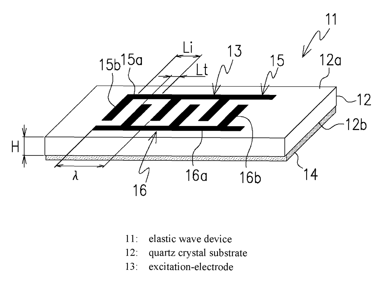
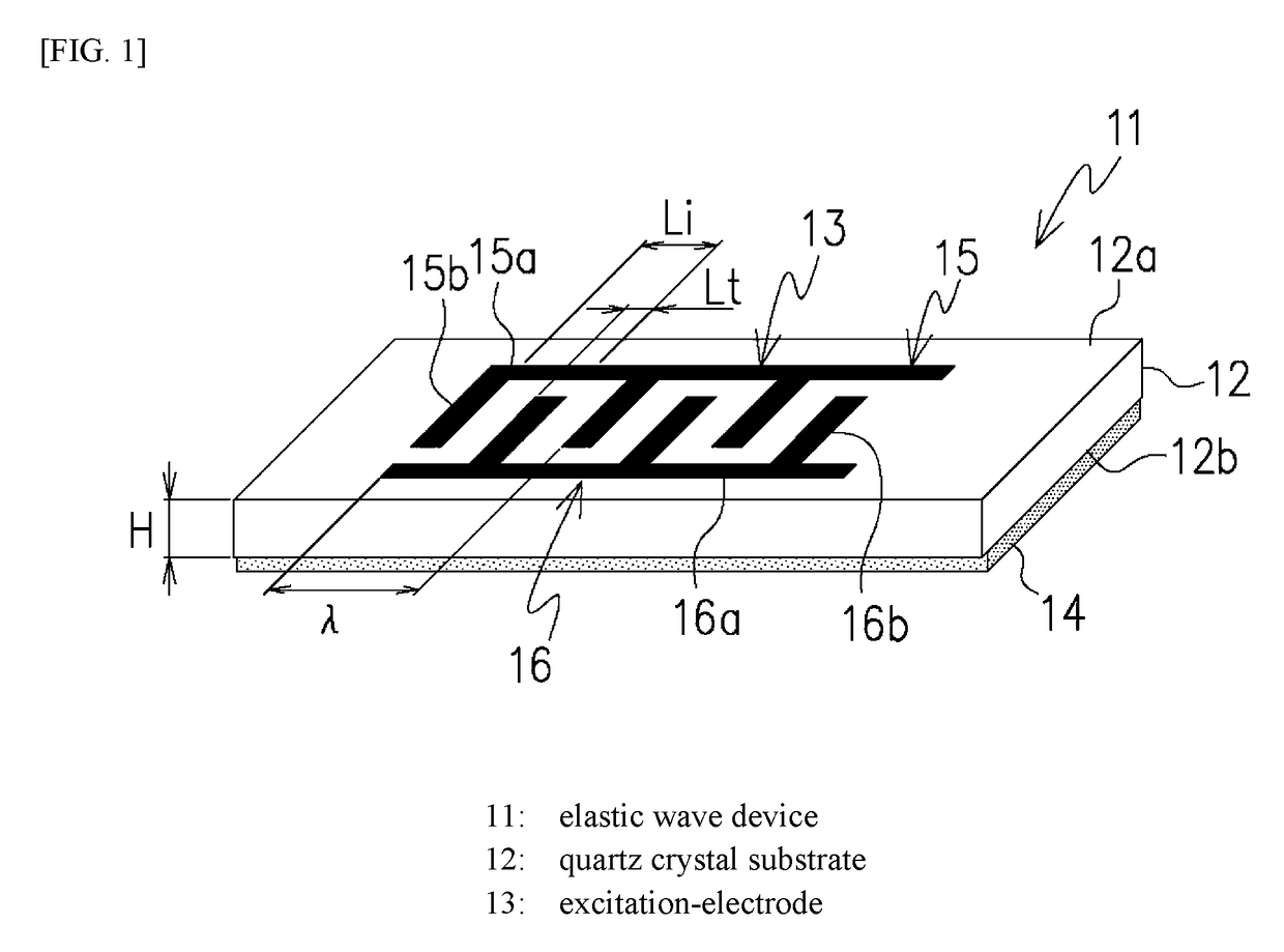
[0085]The following will describe the present invention based on the quartz crystal substrate 12 shown in FIG. 1. The quartz crystal substrate 12 according to this embodiment is cut at rotation angles specified by right-handed Euler angles in the range of (φ=0°, θ=37.6° to 38.3°, Ψ=0°) and has a predetermined substrate-thickness.

[0086]FIG. 9 illustrates dispersion curves of a plurality of plate waves propagating in the quartz crystal substrate 12 with the Euler-angles of (φ=0°, θ=37.6° to 38.3°, Ψ=0°) when Hs / λ=0 and Hb / λ=0.

[0087]The dispersion curves in FIG. 9 are a plurality of vibration modes called a plate wave or a lamb wave, which is the combination of a longitudinal wave and an SV wave. These vibration modes, unlike a surface wave, exhibit frequency dispersion relative to a substrate-thickness. While plate waves includes multiple vibration modes as indicated by those dispersion curves, one of the plate waves that has a phase velocity in the range of 4500 m / s to 6000 m / s is se...

third embodiment

[0101]The following will describe the present invention with reference to FIGS. 16 to 25. As illustrated in FIG. 16, an elastic wave device 21 according to this embodiment includes a quartz crystal substrate 22 including a recessed-portion 36, which opens to one side, on the rear surface of the substrate 22. The elastic wave device 21 also includes an excitation-electrode 23 on the front surface of the substrate 22. A back-electrode 24 may be disposed on the rear surface of the substrate 22 along the surface of the recessed-portion 36. This enables a frequency or other properties to be adjusted accurately.

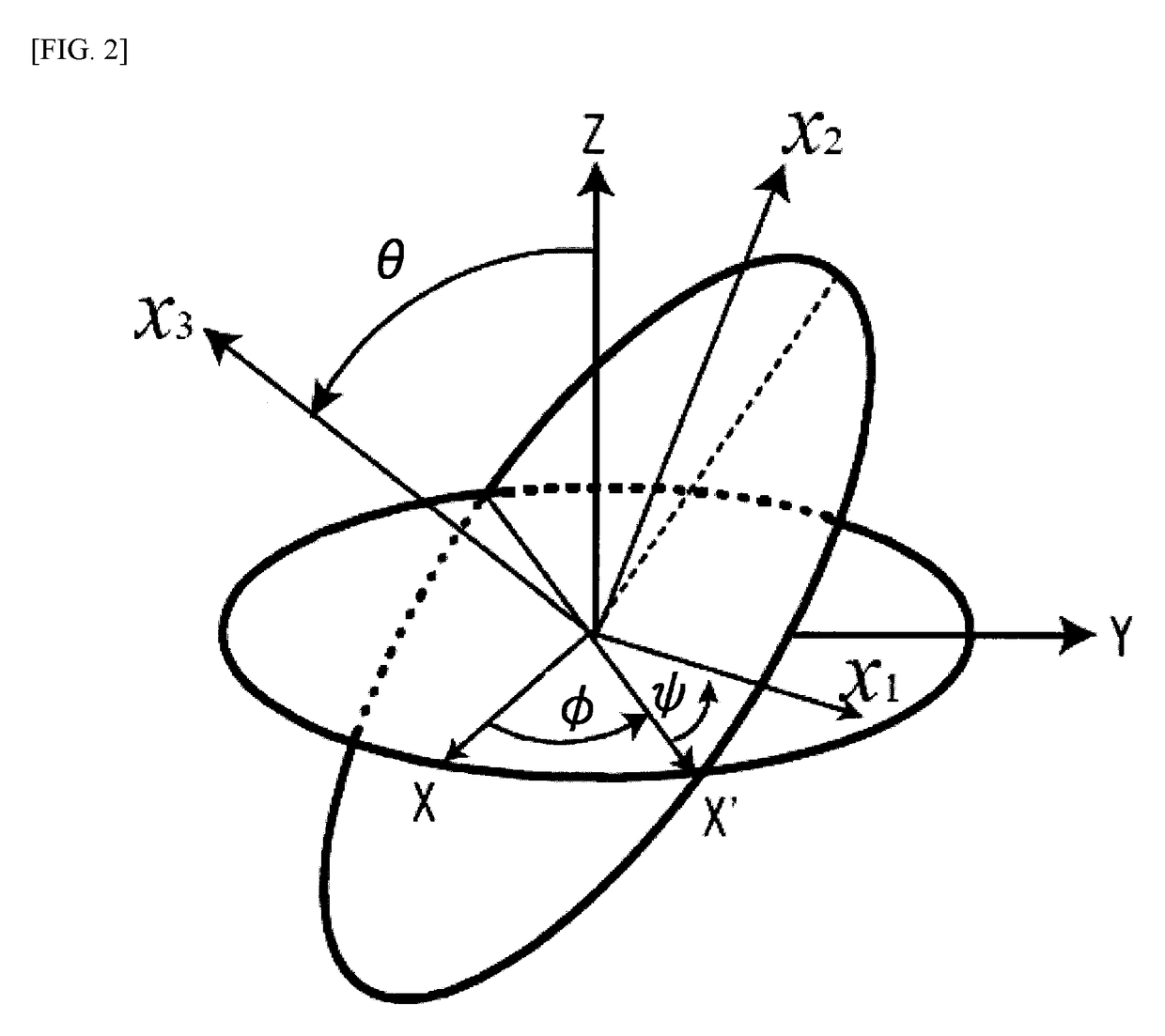
[0102]The quartz crystal substrate 22 is cut from a quartz crystal body with right-handed Euler angles (φ, θ, Ψ) illustrated in FIG. 2. At this step, the quartz crystal body does not include the recessed-portion 36. Then, the recessed-portion 36 is formed on the substrate 22 by etching. In this embodiment, the quartz crystal substrate 22 is cut at the rotation angles in the range o...


PUM


Abstract

An elastic wave device is provided that has an phase velocity optimum for a high-frequency oscillation as well as a preferred frequency temperature behavior that exhibits a cubic curve by utilizing a rotated Y-cut quartz crystal substrate with novel Euler angles of rotation. The elastic wave device includes a quartz crystal substrate and an excitation-electrode. The quartz crystal substrate is cut out from a quartz crystal body that has a particular three-dimensional crystallite orientation. The quartz crystal substrate is cut at rotation angles specified by right-handed Euler-angles. The excitation-electrode generates a plurality of plate waves on a front surface of the quartz crystal substrate. The quartz crystal substrate is cut at rotation angles in a given range. The selected vibration mode of the quartz crystal substrate is a plate wave having a primary and a secondary temperature coefficient in given ranges with Taylor expansion performed at a particular temperature.

Description

TECHNICAL FIELD[0001]The present invention relates to an elastic wave device used in computers, telecommunications equipment, and other electronics as a source of a high-frequency of oscillation.BACKGROUND ART[0002]AT-cut quartz crystal resonators have been commonly used in a variety of electronics as a source of oscillation. To obtain a high-frequency, the frequency of an AT-cut quartz crystal resonator is typically multiplied to a predetermined frequency by a phase-locked loop (PLL). To obtain a low noise signal as well as a high-frequency, a surface acoustic wave device may also be used as a direct source of oscillation.[0003]AT-cut quartz crystal resonators, which can provide stable frequency properties, have been commonly used in many electronics as a source of oscillation. However, an AT-cut quartz crystal resonator needs high-precision processing technique, such as flattening technique and thinning technique, to be used in high-speed computers, telecommunications equipment, a...

Claims


Application Information

Patent Timeline
Patent Type & Authority Patents(United States)
IPC IPC(8): H03H9/02H03H9/17H03H9/145
CPCH03H9/02622H03H9/02228H03H9/171H03H9/02834H03H9/145H03H9/02551
Inventor KON, TASUKUMIZUMOTO, KATSUYA
Owner RIVER ELETEC
Why Eureka
Try Eureka