Laser device

a laser device and laser technology, applied in the direction of laser details, basic electric elements, electrical apparatus, etc., can solve the problems of light source damage, abnormal oscillation, etc., and achieve the effect of preventing abnormal oscillation in the amplifier

Inactive Publication Date: 2013-08-06
FUJIKURA LTD
View PDF5 Cites 0 Cited by
  • Summary
  • Abstract
  • Description
  • Claims
  • Application Information

AI Technical Summary

Benefits of technology

[0017]As described above, according to the invention, a laser device that can prevent abnormal oscillations in the amplifier can be provided.

Problems solved by technology

In a case where an amplifier is provided in the light source, abnormal oscillations might occur in the amplifier, and the light source might be damaged by the high-intensity light generated by the abnormal oscillations.

Method used


Image

  • Laser device
  • Laser device
  • Laser device

Examples


first embodiment

(First Embodiment)

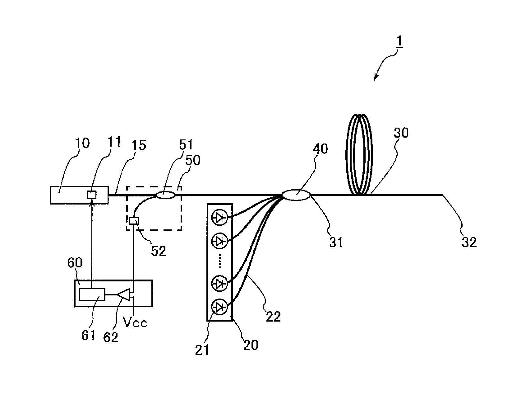
[0022]FIG. 1 is a diagram showing a laser device according to a first embodiment of the invention.

[0023]As shown in FIG. 1, a laser device 1 is a fiber laser device that includes as main components: a seed light source 10 as the light source that outputs seed light as light to be amplified; a pumping light source 20 as the pumping unit that outputs pumping light; an amplification optical fiber 30 as the amplifier to which the seed light and the pumping light are input; a combiner 40 that connects the seed light source 10 and the pumping light source 20 to the amplification optical fiber 30; a monitor unit 50 provided between the seed light source 10 and the amplification optical fiber 30; and a control unit 60 that controls the seed light source 10. Accordingly, the laser device 1 is a so-called MO-PA laser device, with the seed light source 10 being a MO (Master Oscillator), the pumping light source 20 and the amplification optical fiber 30 being a PA (Power Ampli...

second embodiment

(Second Embodiment)

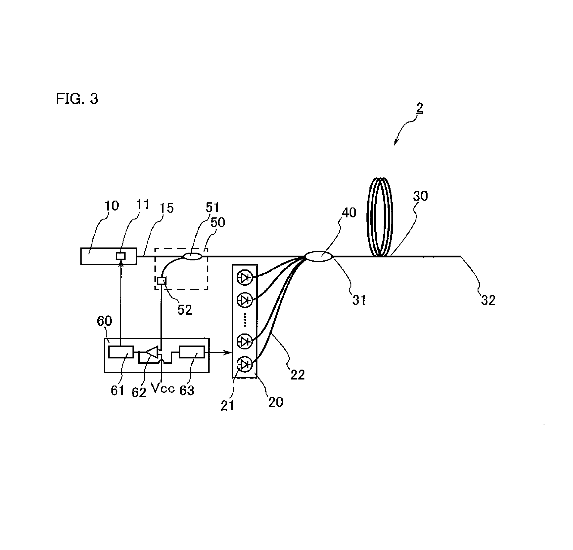
[0044]Referring now to FIG. 3, a second embodiment of the invention is described in detail. It should be noted that components that are identical or similar to those in the first embodiment are denoted by the same reference numerals as those used in the first embodiment, and the same explanation will not be repeated. FIG. 3 is a diagram showing a laser device according to a second embodiment of the invention.

[0045]As shown in FIG. 3, a laser device 2 of this embodiment differs from the laser device 1 of the first embodiment in that the control unit 60 includes a pumping controller 63 that controls the laser diodes 21 of the pumping light source 20. As a result the pumping light that is output from the pumping light source 20 is light based on a control signal from the pumping controller 63. The comparator 62 compares a signal input from the optical detector 52 with a reference voltage, and outputs the result to the light source controller 61 and the pumping contro...


PUM


Abstract

The laser device includes: a seed light source that outputs seed light; a pumping light source an amplification optical fiber as the amplifier that amplifies the seed light with an element pumped by the pumping light source; a monitor unit that is provided between the seed light source and the amplification optical fiber, and monitors the intensity of the light output from the amplification optical fiber; and a light source controller that controls the seed light source. In this laser device, when the light input to the monitor unit has an intensity equal to or higher than a predetermined intensity while the seed light is not input to the amplification optical fiber, the light source controller forces to output the seed light from the seed light source.

Description

TECHNICAL FIELD[0001]The invention relates to laser devices, and more particularly, to a laser device that can prevent abnormal oscillations in the amplifier.BACKGROUND ART[0002]Laser devices are used in the fields of processing machinery, medical equipment, measurement instruments, and the like. With such laser devices, there are cases where output light is reflected by an object to be processed or the like, and the reflected output light is input to the output terminal of the laser device. There has been known laser devices that monitor such reflected light, so as to reduce damage to the laser devices and grasp the condition of the object to be processed.[0003]Patent Document 1 listed below discloses such a laser device. In this laser device, output light that has been reflected by an object to be processed and been input as reflected light to the output terminal is isolated and monitored before reaching the light source.CITATION LISTPatent Document[0004][Patent Document 1] Japane...

Claims


Application Information

Patent Timeline
Patent Type & Authority Patents(United States)
IPC IPC(8): H01S3/30H01S3/13H01S3/00
CPCH01S3/06754H01S3/10015H01S3/10H01S3/09408H01S3/1302H01S2301/02H01S3/13013
Inventor NAKAI, MICHIHIRO
Owner FUJIKURA LTD
Why Eureka
Try Eureka