Objective lens driving apparatus using in optical pick device
A technology of driving device and optical pickup, which is applied in the direction of beam guiding device, head configuration/installation, instrument, etc., and can solve the problems of increasing the width and weight of the objective lens driving device, increasing the cost of the objective lens driving device, etc.
- Summary
- Abstract
- Description
- Claims
- Application Information
AI Technical Summary
Problems solved by technology
Method used
Image

Examples
no. 1 example
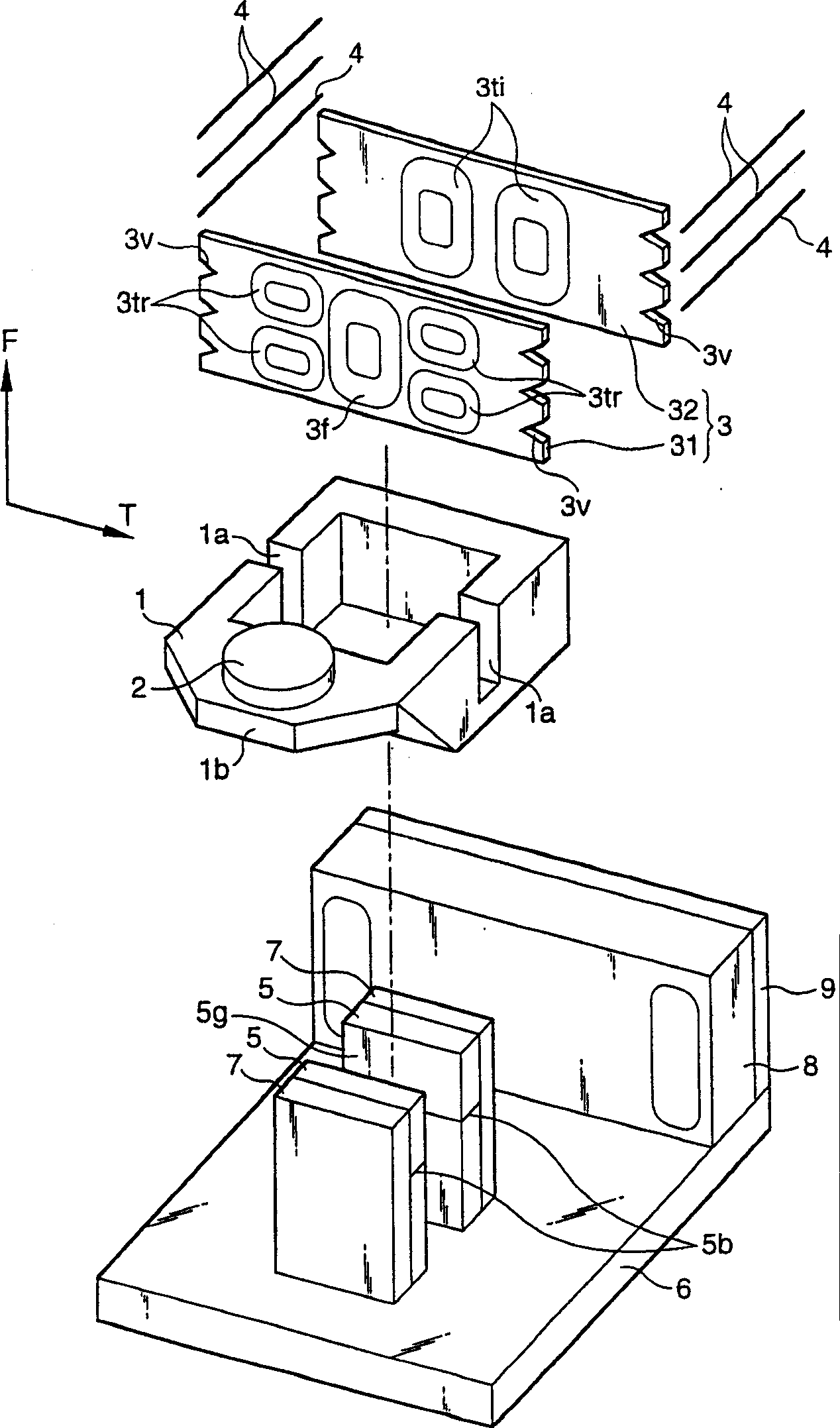
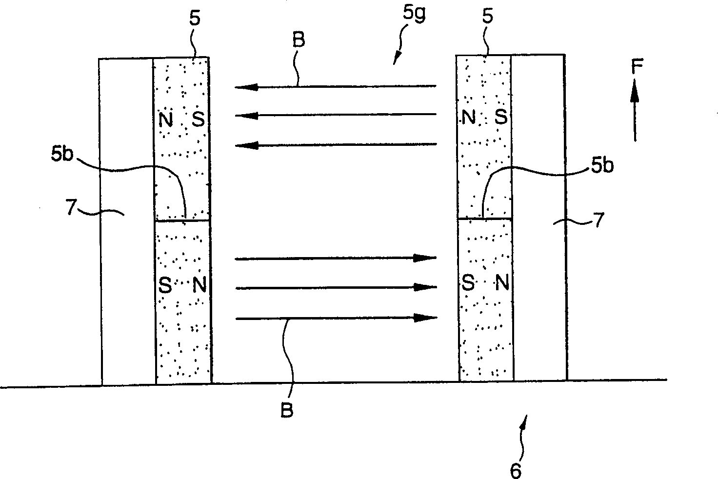
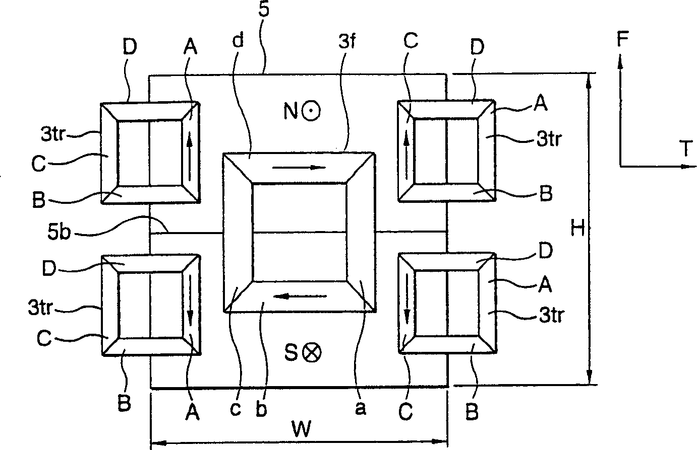
[0049] Now, figure 1 is an exploded perspective view of the first embodiment of the objective lens driving device used in the optical pickup according to the present invention. exist figure 1 , the contents of the reference characters are as follows: reference character 1 represents the lens holder, 2 represents the objective lens, 3 represents the coil unit, 3f represents the focusing coil, 3tr represents the tracking coil, 3ti represents the tilt coil, 5 represents a magnet, 5g represents a magnet Gap.
[0050] The lens holder 1 is made of flexural elastic high modulus light metal such as magnesium alloy, or made of resin mixed with carbon fiber. Using such a material makes the lens holder 1 itself have a higher flexural elastic modulus, so that it has a higher high-order resonance frequency. Because of this, the lens holder 1 can withstand the increase in the speed of the optical disc unit.
[0051] In the lens holder 1, two notch portions 1a are formed, both of which...
Embodiment 2
[0072] Now, Figure 11 is a perspective view showing a second embodiment of the objective lens driving device according to the present invention. exist Figure 11 In , the meanings of the reference characters are respectively expressed as follows: 101 represents a lens holder, 102 represents an objective lens, 103 represents a coil unit, 103f represents a focusing coil, 103tr represents a tracking coil, 103ti represents a tilting coil, 105 represents a magnet, 105 represents a magnetic gap.
[0073] The lens holder 101 is made of flexural elastic high modulus light metal such as magnesium alloy, or made of resin mixed with carbon fiber. Using such a material makes the lens holder 101 itself have a higher flexural elastic modulus, thus having a higher high-order resonance frequency. Because of this, the lens holder 101 can withstand the increase in the speed of the optical disc unit.
[0074] Referring to another structure of the disc holder 101, on its plane, two slits 111...
Embodiment 3
[0097] Now, Figure 18 is a perspective view of a third embodiment of the objective lens driving device according to the present invention. exist Figure 18 In , the meanings of the reference symbols are as follows, 201 represents a lens holder, 202 represents an objective lens, 203 represents a coil unit, and 205 represents a magnet.
[0098] The lens holder 201 is similar in structure to the lens holder 1 employed in the first embodiment described above.
[0099] The coil unit 203 includes a required number of printed circuit boards 203p stacked one on top of the other, and each printed circuit board 203p includes a tracking coil 203t and four focusing coils 203fl and 203fr. The tracking coil 203t is located in the center of the printed circuit board 203p, and the focusing coils 203fl and 203fr are located in the upper and lower sections, and relative to the position of the center of gravity of the objective lens optical axis direction of the moving parts, they are located...
PUM
 Abstract
Description
Claims
Application Information