Rubber coated strand, belt, ply, tire using it, production device and method for them
A manufacturing method and a manufacturing device technology, which are applied in the field of rubber film-coated strand manufacturing devices, can solve the problems of reduced tensile strength of strands, deterioration of wire stranding and bending properties, and inability to guarantee displacement, and achieve improved stability. properties, suppressing frictional heat, and improving corrosion resistance
- Summary
- Abstract
- Description
- Claims
- Application Information
AI Technical Summary
Problems solved by technology
Method used
Image
Examples
no. 1 example
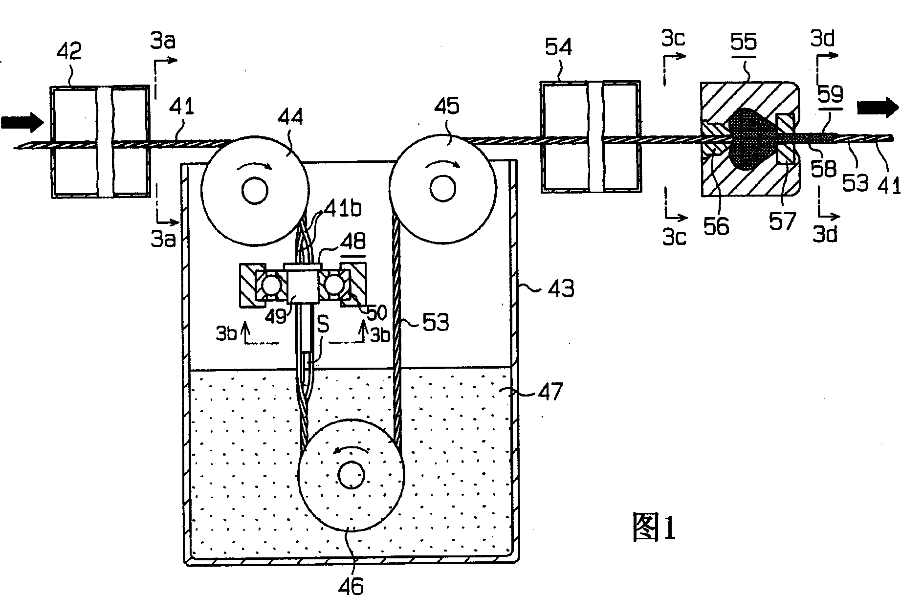
[0087] A first embodiment of the present invention will be described below with reference to FIGS. 1 to 3 .
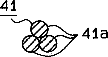
[0088] As shown in FIG. 1, in the rubber film-coated strand manufacturing apparatus according to the first embodiment of the present invention, the strand 41 is conveyed longitudinally at a predetermined speed by a conveying mechanism not shown in the figure. As shown in Figures 1 and 3(a), the strand 41 is composed of three wires 41a twisted by a known method. The wire 41a is made of metal such as steel. Electroplating such as tin plating may be performed on each wire 41a as an undercoating treatment to improve rubber adhesion. Each wire 41a has a uniform, circular cross-section.
[0089] A preheating chamber 42 as a preheating device is provided in the conveyance path of the strand 41 . In this preheating chamber 42 the strands 41 are preheated. Instead of preheating, the strands 41 may be washed or coated with an adhesion promoter as pretreatment.
[0090] Down...
no. 2 example
[0105] Next, a second embodiment of the present invention will be described. The difference from the first embodiment is mainly introduced.
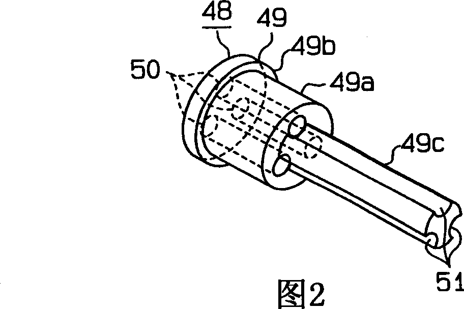
[0106] In the second embodiment, as Figure 4 As shown, strand 41 is formed by twisting three wires 41b in a known manner. The thread 41b is made of a polymer material such as polyester and nylon. During the priming process, an adhesive coating is applied to each wire 41b so that each wire 41b is sufficiently bonded to the rubber. The structure of the rotor 49 of the untwisting device 48 is the same as that of the first embodiment, and the rotor is rotatably supported in the liquid rubber pool 43 through the metal bearing 61 . The driven gear 62 is mounted on the upper end of the liquid rubber pool 43 . Inside the liquid rubber pool 43 is a drive motor 63 as a rotation means. A drive gear 64 meshing with a driven gear 62 is on the motor shaft.
[0107] The strands 41 are separated and conveyed through openings 51 and corresponding ...
no. 3 example
[0114] The following will refer to Figure 5 and 6 introduce a third embodiment of the present invention. The differences from the above embodiments are mainly introduced.
[0115] In the third embodiment, as shown in FIG. 6( a ), a strand 41 is formed by twisting six wires 41 a or 41 b around a central wire in a known method. Each wire 41a or 41b is made of metal material or polymer material.
[0116] Such as Figure 5 with 6(b) As shown, a central opening 51A is formed through the center of the rotor 49 of the untwisting device 48 so that the filaments pass through the hole separately. Six outer side openings 51B are formed through the main body 49a and the flange 49b of the rotor 49 and are spaced apart from each other by a predetermined distance. The outer side opening 51b is arranged to surround the central opening 51A. Six grooves 52 are formed on the outer periphery of the small-diameter projecting portion 49c of the rotor 49 and are spaced apart from each other b...
PUM
 Abstract
Description
Claims
Application Information
 - R&D
- Intellectual Property
- Life Sciences
- Materials
- Tech Scout
- Unparalleled Data Quality
- Higher Quality Content
- 60% Fewer Hallucinations
Browse by: Latest US Patents, China's latest patents, Technical Efficacy Thesaurus, Application Domain, Technology Topic, Popular Technical Reports.
© 2025 PatSnap. All rights reserved.Legal|Privacy policy|Modern Slavery Act Transparency Statement|Sitemap|About US| Contact US: help@patsnap.com


