Consumable electrode type arc welding method and device therefor

An arc welding method and arc welding technology, applied in arc welding equipment, welding equipment, manufacturing tools, etc., can solve the problems of unstable arc, large sputtering, large welding current, etc., and achieve the effect of stable arc state

Inactive Publication Date: 2002-04-10
YASKAWA DENKI KK
View PDF2 Cites 19 Cited by
  • Summary
  • Abstract
  • Description
  • Claims
  • Application Information

AI Technical Summary

Problems solved by technology

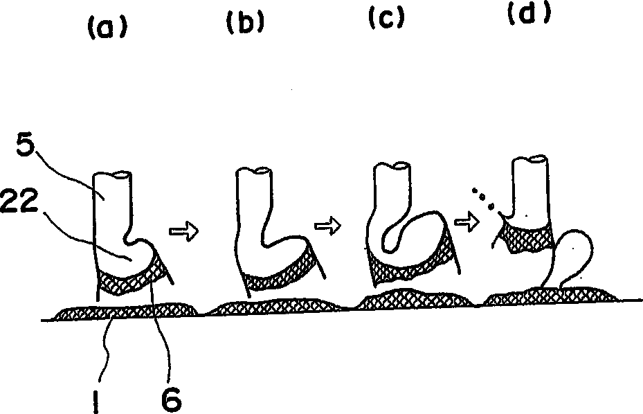
[0008] (1) Since the weld droplet 22 moving from the tip (tip) of the welding wire 5 to the base material 1 becomes a large particle, there is a case where the weld droplet 22 moves to a place other than the melting pool and becomes sputtering of a large particle
[0009] (2) Since the generated spatter becomes larger, it takes time to remove the sputter attached to the base material 1, and the deposition efficiency from the welding wire 5 to the welding place is reduced, and the welding efficiency is reduced.
However, since the welding current is large, that is, from 300A to 400A in welding above about 2m / min, the melting speed of the welding wire is accelerated, and a large number of welding droplets are generated, and there is a problem of arc instability

Method used


Image

  • Consumable electrode type arc welding method and device therefor
  • Consumable electrode type arc welding method and device therefor
  • Consumable electrode type arc welding method and device therefor

Examples


Embodiment Construction

[0030] Hereinafter, examples of the present invention will be described. Figure 4 It is a relational diagram of welding voltage, welding current, welding wire feeding speed, and droplet movement in the present invention.

[0031] Such as Figure 4 As seen in , if a short circuit occurs, the voltage drops from a set value, and a short circuit is detected, then, after a predetermined delay time, the welding current is increased to release the short circuit. In addition, by decelerating the welding wire feed speed in synchronization with short circuit detection, molten metal flow or surface tension in the molten pool effectively plays a role in detachment of the droplet from the wire tip and promotes short circuit release. After the short circuit is released, the welding wire feeding speed is accelerated to prevent the droplet from breaking away from the generated arc fragments, and the movement to the arc and the formation of the droplet are performed rapidly. Here, by equali...


PUM


Abstract

The present invention provides simple and inexpensive welding method and apparatus adapted to extremely reduce spatters occurring and scattering during a welding operation, even in a welding operation carried out at not lower than substantially 2 m / min. The consumable electrode type arc welding apparatus according to the present invention is provided with a welding power source 23 for controlling a welding current and a welding voltage, a unit 25 for feeding a welding wire to a base metal, a unit 26 for giving the welding wire feeding unit an instruction to feed the welding wire, on the basis of a signal from a short-circuiting / short-circuiting cancellation detector 29, a welding condition setter 24 for setting the welding condition, a welding speed setter 27, a unit 28 for moving a welding torch in accordance with the welding speed, and the short-circuiting / short-circuiting cancellation detector 29 for detecting short-circuiting or short-circuiting cancellation.

Description

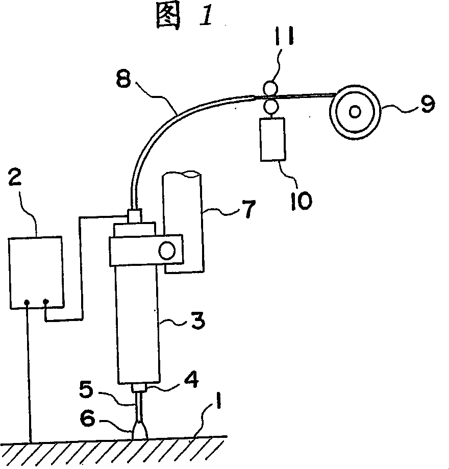
technical field [0001] The present invention relates to a melting electrode arc welding device. Background technique [0002] Conventionally, when welding is performed by gas shielded arc welding or the like, a welding apparatus as shown in FIG. 1 is used. In the figure, 1 is the base metal to be welded, 2 is the welding power supply, 3 is the welding torch, 4 is the tip of the welding torch, 5 is the welding wire, 6 is the welding arc, 11 is the welding wire feeding drum, and 10 is the welding wire feeding The driving motor for the drum, 9 is a winding wire reel, 7 is a fixed arm of a simple trolley (not shown) that fixes the welding torch 3, or the arm of a welding robot, and 8 is used to supply the welding wire 5 to the welding machine. Conduit cable for mouth 3. [0003] In the case of welding by such a welding device, at first, if an appropriate voltage is supplied from the welding power source 2, a welding arc 6 is generated between the tip of the welding wire 5 and ...

Claims


Application Information

Patent Timeline
IPC IPC(8): B23K9/095B23K9/12
CPCB23K9/124B23K9/0956B23K9/12
Inventor 古贺靖弘奥村信治平山卓秀仁尾理中岛春树三田常夫
Owner YASKAWA DENKI KK
Why Eureka
Try Eureka