Display and its drive method

A technology of a display device and a driving method, applied in static indicators, nonlinear optics, instruments, etc., capable of solving problems such as increased power consumption, increased gate driver power supply voltage, and increased TFT size

Inactive Publication Date: 2002-04-17
SANYO ELECTRIC CO LTD
View PDF1 Cites 5 Cited by
  • Summary
  • Abstract
  • Description
  • Claims
  • Application Information

AI Technical Summary

Problems solved by technology

[0018] However, ① there is a disadvantage that the power consumption increases due to the increase in the power supply voltage of the external circuit
② There are disadvanta

Method used


Image

  • Display and its drive method
  • Display and its drive method
  • Display and its drive method

Examples


Embodiment Construction

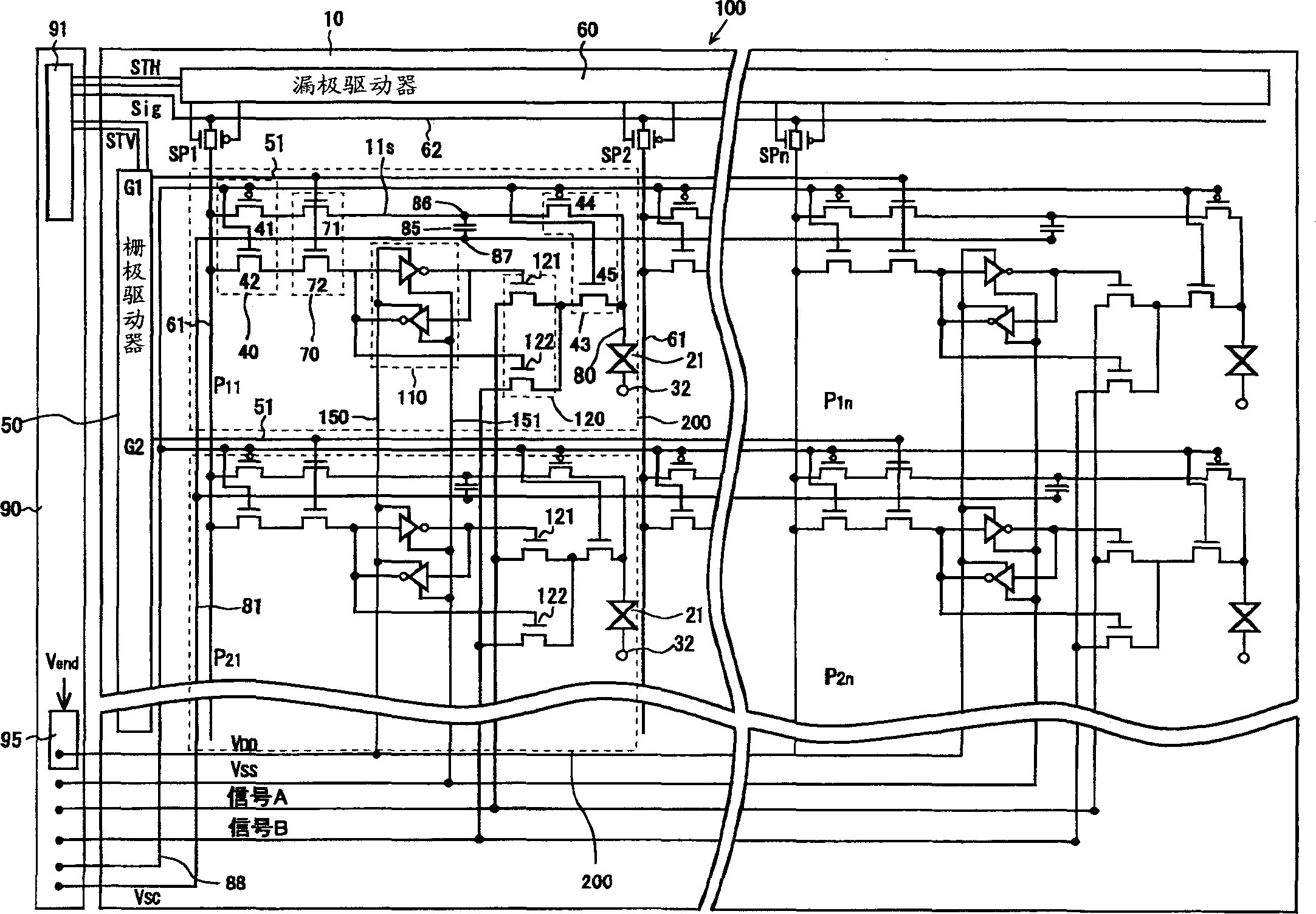
[0038] Embodiments of the present invention are described below. figure 1 A circuit configuration diagram showing the liquid crystal display device of the first embodiment.

[0039] On the insulating substrate 10 , a plurality of gate signal lines 51 connected to a gate driver 50 supplying scanning signals are arranged in one direction, and a plurality of drain signal lines 61 are arranged in a direction crossing the gate signal lines 51 .

[0040] Sampling transistors SP1 , SP2 , .

[0041] The liquid crystal display panel 100 is constituted by a matrix arrangement of a plurality of display pixels 200 selected by scanning signals from gate signal lines 51 and supplied with data signals from drain signal lines 61 .

[0042]Hereinafter, a detailed structure of the display pixel 200 will be described. Near the intersection of the gate signal line 51 and the drain signal line 61, a circuit selection circuit 40 composed of a P-channel type TFT 41 and an N-channel type TFT 42 is...


PUM


Abstract

The present invention provides a display device and its driving method to prevent the occurrence of erroneous writing of data into a holding circuit 110, to reduce power consumption and to provide highly integrated display pixels. In a display device which is provided with holding circuits to sustain digital video data for display pixels, the power supply voltage supplied to the holding circuits 110 is set to a minimum level that is an absolute minimum for sustaining the data. The power supply voltage to be supplied to the circuits 110 is boosted by a boosting circuit 95 after completion of the writing. In accordance with the signals inputted from gate signal lines 51, digital video signals from drain signal lines 61 are written into the circuits 110 and the circuits 110 sustain the signals. Displaying is conducted in accordance with the signal sustained in the circuits 110.

Description

technical field [0001] The invention relates to a display device and a driving method thereof, in particular to a display device suitable for a portable display device and a driving method thereof. Background technique [0002] In recent years, the market requires portable display devices, such as portable televisions and mobile phones. In response to such needs, research and development for miniaturization, light weight, and low power consumption of display devices are being actively carried out. [0003] Figure 7 A circuit configuration diagram showing a display pixel of a conventional liquid crystal display device. On an insulating substrate (not shown), gate signal lines 51 and drain signal lines 61 are formed to intersect, and TFTs 65 connected to both signal lines 51 and 61 are provided near the intersections. The source electrode 11s of the TFT 65 is connected to the display electrode 80 of the liquid crystal 21 . [0004] In addition, a...

Claims


Application Information

Patent Timeline
IPC IPC(8): G02F1/133G09G3/20G09G3/30G09G3/36
CPCG02F1/1368G09G3/32G09G3/3614G09G3/3648G09G2300/0408G09G2300/0809G09G2330/021
Inventor 米田清横山良一
Owner SANYO ELECTRIC CO LTD
Why Eureka
Try Eureka